After the registers and the ALU, the program counter module was pretty easy. It
is a 74LS161 4-bit binary counter connected to a 74LS245 8-bit transceiver. As
with the other modules, the transceiver is only there to easily control reading
or writing to the bus.
Using a binary counter IC to build a program counter may seem like cheating,
but there’s no reason to make everything harder than it needs to be. The
counter’s output and input are wired to the transceiver, the enabled pin is put
high, connect the clock, and you’re good to go…
Well, that’s what the instructions said. Whenever I tried to run the counter it
kept flashing “one”. After a few seconds of feeling crushingly defeated on what
was supposed to be the easiest build of the project, I thought it felt like the
counter was being constantly reset. I looked at the chip’s data sheet and saw
that pin 1 is the clear pin. We hadn’t wired it to anything so it was floating.
The pin is inverted, so I tried tying it high. Lo and behold, the counter now
works.
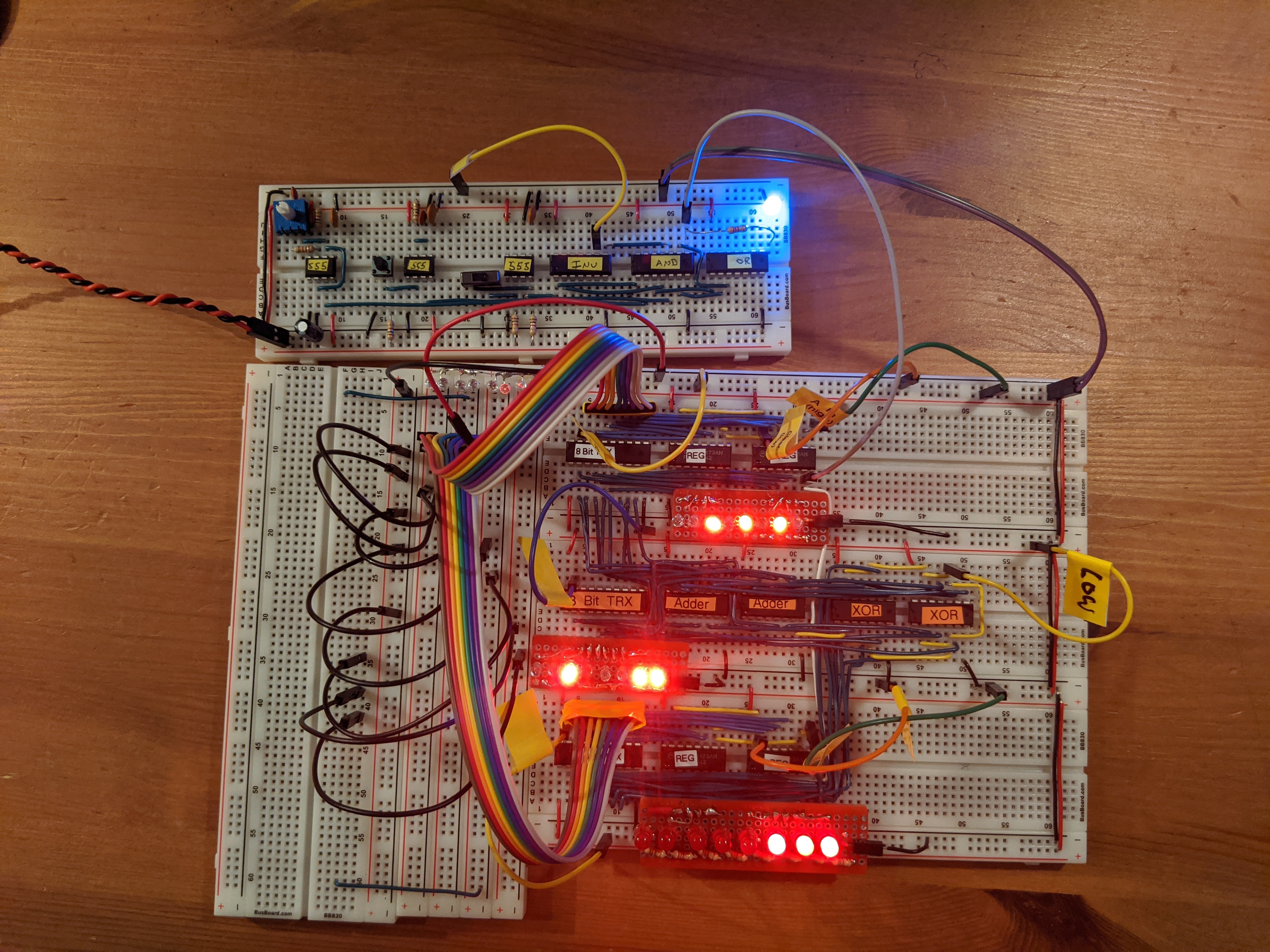
I still need to wire up some permanent lights for the module. The ones in the
video are part of the pack of lights I wired up for quick testing last time (or
the time before that… sometime). They have resistors built in and just have a
pair of pin Dupont connectors on the bottom so I can easily plug them in
anywhere I want.
Now that I have two registers to store whatever (8-bit) values I want in them, what next? Let’s add them together! (Or subtract them).
The ALU
The ALU reads directly from the A and B registers and computes the sum of those two values. It bypasses the bus and reads directly from the registers, whether or not they are set to output their values. The ALU has two modes, add and subtract.
In subtract mode (when the control line is brought high), it subtracts the value in register B from register A. Subtraction works by negating the output of the B register and then adding that negative number to A. Two’s Complement is used to represent a negative number in binary. This pretty much boils down to flipping all the bit and then adding one. Eight XOR gates are used to flip the bits (the subtract signal is the other input to the gate) and then add one by setting the carry bit on the adder high. The carry bit is normally used when using multiple 4-bit adder chips together to add 8 bits together (or 12 or 16… etc).
Building and Debugging
So far this is has been the most complicated part of the computer to build. This is purely because of the number of connections to be made and how much they overlap. If you’re off by one pin for one wire the entire output is messed up and you have to wade through all the criss crossing wires to figure out what is wrong. The problem gets worse when you have multiple wires in the wrong spot… which is what happened to me.
I learned two useful approaches to this problem
Write out a table of all of the connections
Use a multimeter to test for voltage levels in addition to continuity
Tabling Connections
In order to know which if a wire is connecting the wrong pins on two IC’s, you need to know which are the right pins. So after blindly staring at the forest of wires, I went back to the pin outs of the IC’s and wrote a few tables to track what I should expect to be where. I did them by hand in a notebook, but this is essentially what I have.
The A Input
The A register is simpler than the B register since it connects directly to the adder and does not need to be negated.
A Register Bit
A Transceiver Pin
Adder Pin Name
Adder Pin
8
2
A4
Left 12
7
3
A3
Left 14
6
4
A2
Left 3
5
5
A1
Left 5
4
6
A4
Right 12
3
7
A3
Right 14
2
8
A2
Right 3
1
9
A1
Right 5
This basically just tells me that if I think I’m having an issue with the most significant bit in the A register (bit 8), then I need to check to see if the wire from the transceiver’s second pin connects to the twelfth pin on the left adder. Once I run down all the pins combinations to make sure that they are correct, I can be confident that the register is wired up correctly and move on to the B register.
The B Input
As alluded to above, the B register is a touch more complicated because it goes through a set of XOR IC’s as well.
B Register Bit
B Transceiver Pin
XOR Pin Name
XOR Pin
8
2
A4
Left 12
7
3
A3
Left 9
6
4
A2
Left 4
5
5
A1
Left 1
4
6
A4
Right 12
3
7
A3
Right 9
2
8
A2
Right 4
1
9
A1
Right 1
The other input pins on the XOR chips were easy and didn’t really require a complex table. All of the B pins were connected to eachother and then the carry in bit on the rigth adder
Pin Name
XOR Pin
XOR B4
Left 14
XOR B3
Left 10
XOR B2
Left 5
XOR B1
Left 2
XOR B4
Right 14
XOR B3
Right 10
XOR B2
Right 5
XOR B1
Right 2
Adder Carry In
7
And then the output of the XOR chips feeds back into the two adders
B Register Bit
XOR Pin Name
XOR Pin
Adder Pin Name
Adder Pin
8
Y4
Left 11
B4
Left 11
7
Y3
Left 8
B3
Left 15
6
Y2
Left 6
B2
Left 2
5
Y1
Left 2
B1
Left 6
4
Y4
Right 11
B4
Right 11
3
Y3
Right 8
B3
Right 15
2
Y2
Right 6
B2
Right 2
1
Y1
Right 2
B1
Right 6
One of the bigger mistakes here is that I wired the left XOR to the right adder. Not sure why I was so certain that was the right thing to do at the time but I did it consciously and certain that it would work out.
Adder Output
And now all that we need to do is wire the adder outputs to the transceiver.
Summation Bit
Output Transceiver Pin
Adder Pin Name
Adder Pin
8
2
Left Σ4
Left 11
7
3
Left Σ3
Left 15
6
4
Left Σ2
Left 2
5
5
Left Σ1
Left 6
4
6
Right Σ4
Right 11
3
7
Right Σ3
Right 15
2
8
Right Σ2
Right 2
1
9
Right Σ1
Right 6
Using a Multimeter
The most straightforward way to use the multimeter to verify the connections is to use the continuity feature:
Turn on the multimeter
Put the red lead on one pin
Put the black lead on the pin you hope it’s connected to (this is where the charts come in handy)
If you hear a tone, then the wiring is good. If you don’t, then you found a problem. Move the black lead to other pins to determine which pin the other end of the wire is connected to. Even if there was a tone, it may be useful to place the black lead on other pins to check for a short. This would mean that another wire connected to this IC is incorrect.
The upside of this approach is that it is simple. The downside is that it requires testing every connection. This is a pretty simple layout and it has upwards of forty connections to check. Another option is to do voltage reading to test which connections have voltage running through them. This is essentially the same as hooking up an LED in parallel to each of the pins to see its output. Set the multimeter to 5v DC setting, put the black wire to ground, and then put the red wire on the IC pin. I like to use alligator clamps coming out of the multimeter connected to jumper wires. That way the wires can be plugged directly into the breadboard and you can monitor voltages as the state changes.
Output
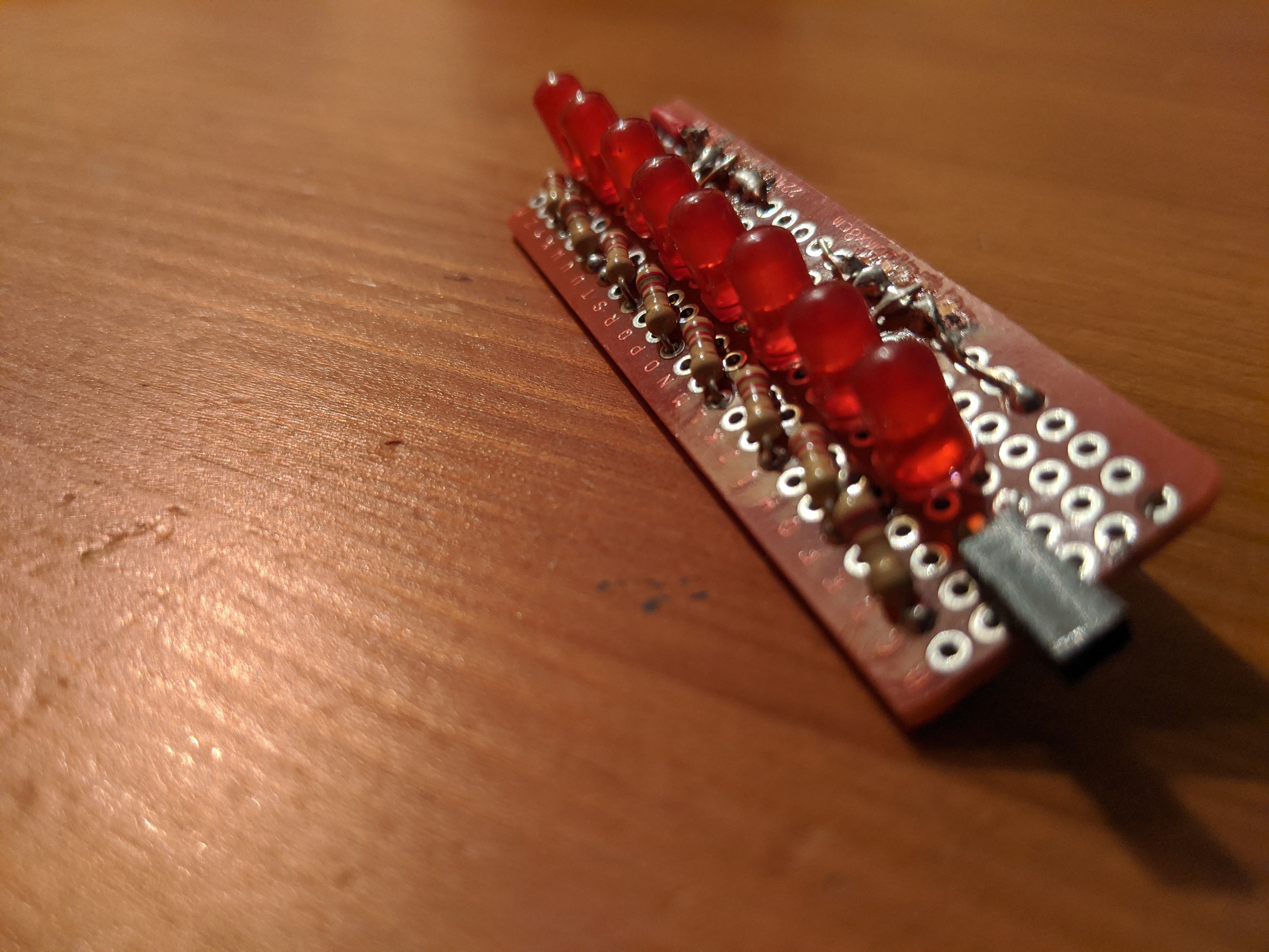
The final component here is wiring up LED’s. I decided it would be easiest to read the output if I made more LED strips that could plug into the breadboard with headers. I’ve improved on the original design by using LED’s with with the resistors built in. This reduces the amount of soldering I need to do and makes the result a little more compact. Speaking of which, I also used 3mm LED’s instead of the original 5mm.
I’ve finished the registers for y project of building an 8-bit computer using TTL chips. I have built two general purpose registers (an “A register” and a “B register) as well as the instructor register for the computer. This step took a lot more time than the clock module. The main difficulties were cutting the wires to the correct size and then after that the thing just didn’t work. I couldn’t store or transfer any data.
What is a Register?
So what exactly did I build in the past few weeks? The computer I’m working on will have a certain amount of RAM to store information during the execution of a program. This information is both the data in the program as well as the program itself. For example, I can write a program that will add the numbers 2 and 4. The values 2 and 4 will be stored in RAM when the program is loaded into the computer. In addition to that, the program itself will be stored in memory. In a modern computer, the program would be stored on the hard drive, but it would eventually be loaded into RAM before it executes, and the data would probably be entered by a user. My computer won’t have either a hard drive or any form of user input. It will all just be stored directly in RAM.
Following the 2 plus 4 example, my computer can’t operate directly on the data in RAM. It can only add (or subtract) numbers that are stored in the registers. This means that we’ll need to copy the data from their location in RAM into either the A or B register. Once there the arithmetic-logic unit (the next part of the build) can operate on them. Basically, the register is short term storage for data being used very soon.
There are three operations you can do with a register:
Write to it
Read from it
Clear it
Normally, you can’t easily inspect the data currently in the register. That would be boring and make it super hard to understand what’s going on at any given time in the computer. These registers have 8 red LED’s that will show the current state of the register.
Transferring data from one register to another (or to another part of the computer), that data is written and then read from the bus. The bus is pretty simple component that wires all the components together using 8 parallel input/outputs. Coordination is required so that only one thing is writing to the bus at a given time and that the component that wants that data is reading from it. For now that’s done manually, but wiring in that logic will be an important part of what makes this a computer.
Cutting Wires
Last time, I built the clock module for my 8-bit computer and I had a hell of a time cutting and stripping the wires just right. I could reliably cut the wires the right length, but then I couldn’t take off exactly 0.3” of insulation on either side using my strippers. I had two options: get good or buy more reliable strippers.
I went with the latter and picked up a set of Knipex wire strippers. These things are amazing. Set the length to strip, insert wire, pull trigger, repeat. The exact right amount is stripped each and every time. No worries about setting the right gauge wire, it auto adjusts. Pure joy to work with after fumbling around last week. I can now complete wiring tasks in minutes that would take hours without them.
They are a little on the pricey side but they will save me so much time and effort that they are worth it. I’d highly recommend them if you can afford it.
The Build
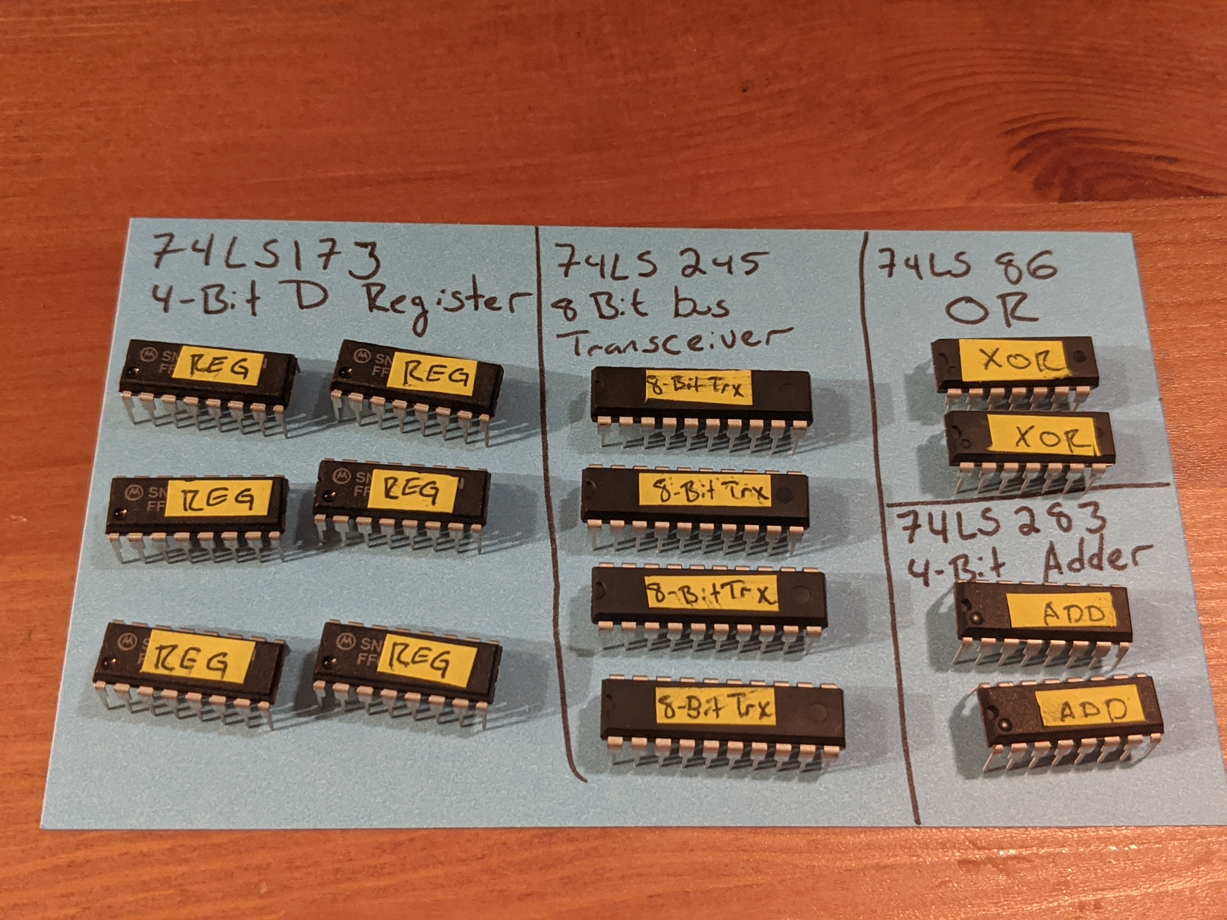
Each register uses :
2 4-bit 74LS173 (register)
1 8-bit 74LS245 (transceiver)
The remaining transceiver, OR gates, and adders in the picture will be used for the ALU.
The register chips are 4 bits each, which is why two are needed to store 8 bits total. They are wired together (clocks, read signal, output signal, etc) so that they can be used as a single logical unit. They are wired to always output their data so that we can see their state in the LED’s. That’s why the transceiver is needed to toggle writing that state to the bus when the computer needs to read from the register.
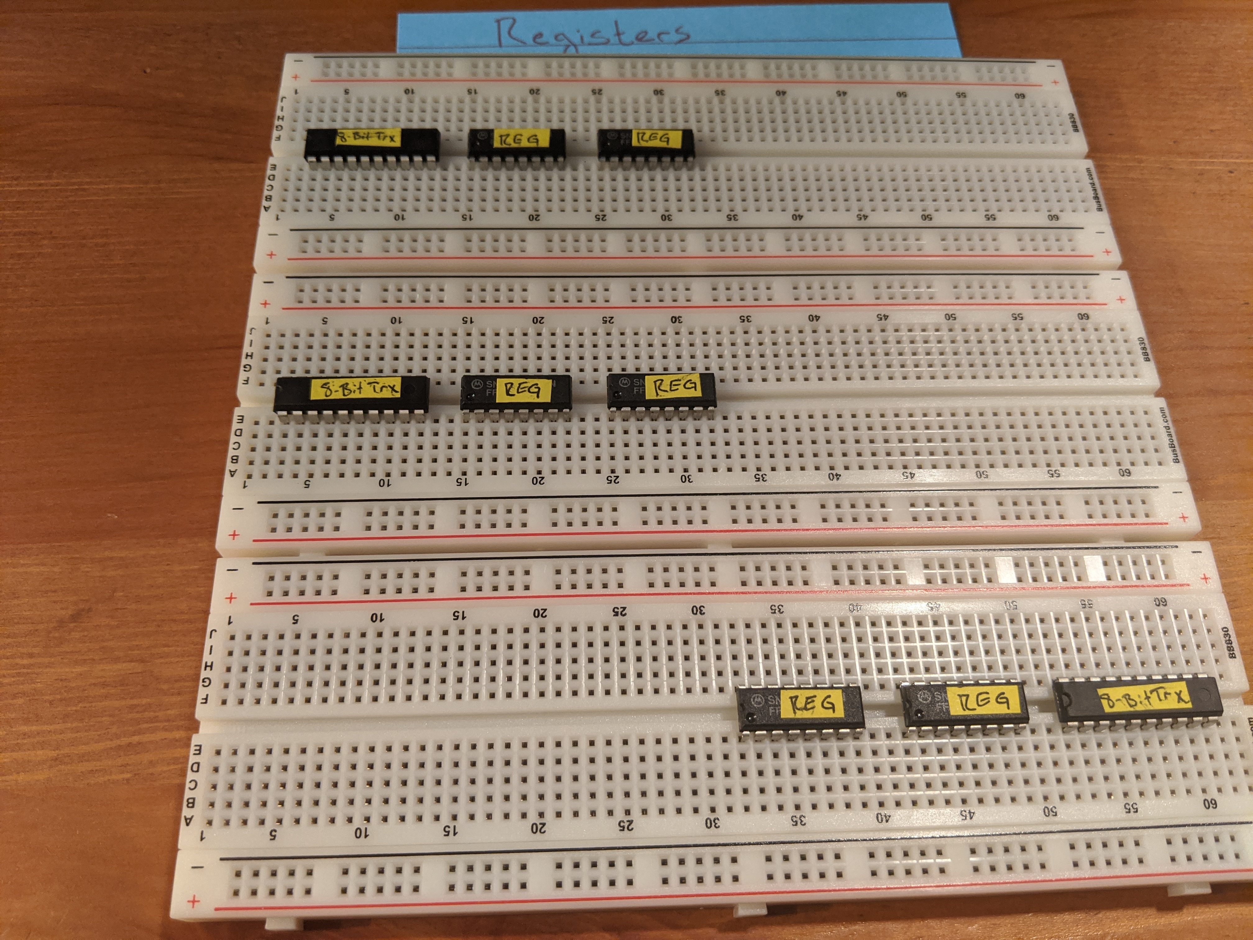
Each breadboard will be dedicated to a register. The top two will be the A and B registers, the bottom one will be used for the instruction register. The top two will be on the right side of the computer, the bottom one will be on the left. The transceiver chip will need to be connected to the bus (which will be in the middle) so it will be convenient to have that as close to the bus as possible (just to avoid messy wiring). Other than that, the three registers will be identical
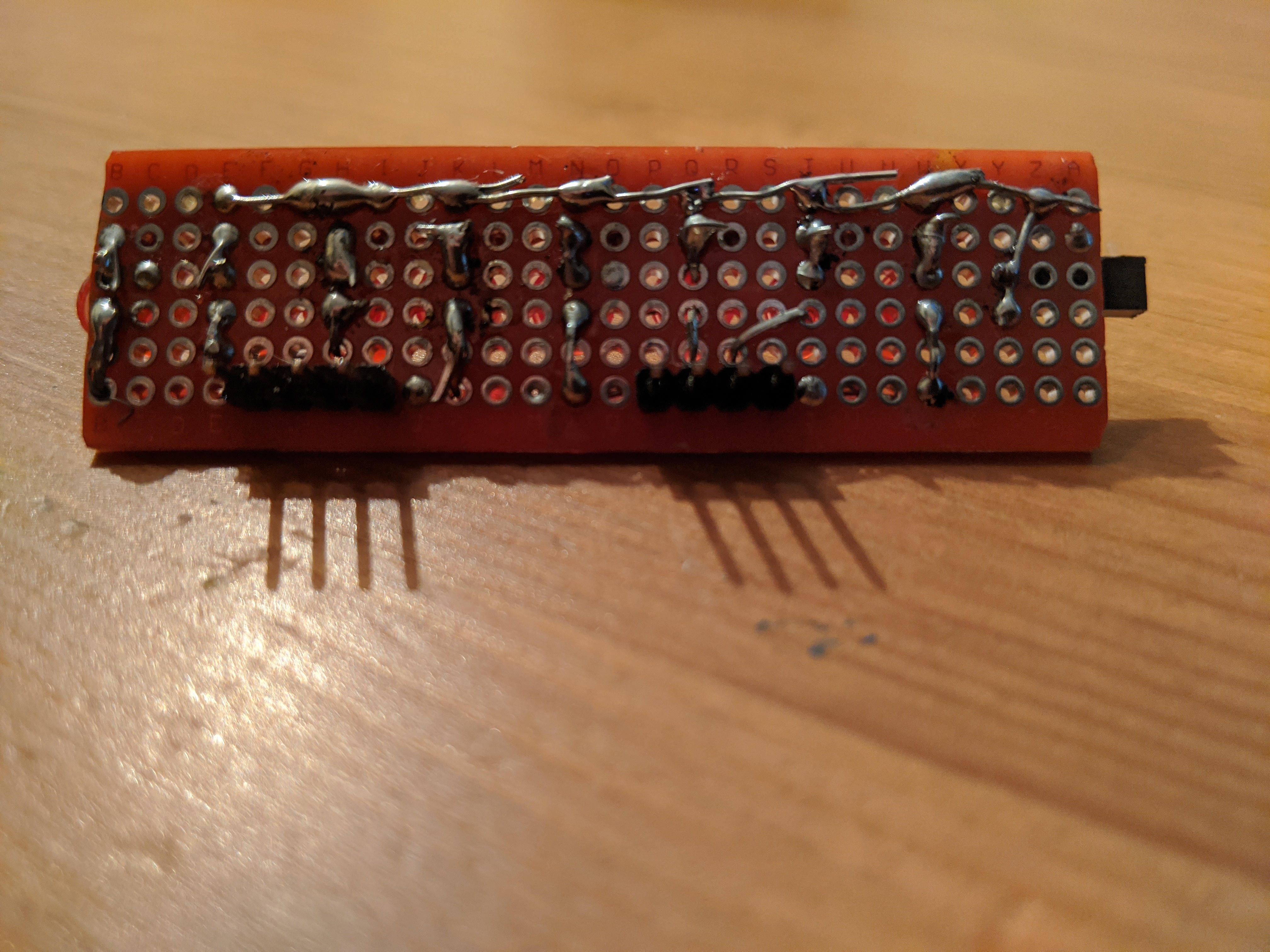
Here we can see the connections keeping the pairs of register chips in sync with each other. The white wires (on the bottom) will be used as the clock input, the yellows are signals to read or clear data.
The rest of the work is to just wire up the 8 channels connecting the registers and transceivers.
LED’s
After wiring everything up and testing it by trying to read off of a mocked out bus … Nothing worked.
I spent hours following the video checking and rechecking my connections. Everything looked right. Reading r/beneater had a lot of posts about how important resistors are to the project despite being largely omitted from the videos. So I tried adding some in series to the LEDs to see if it would make a difference. Yes it did! Everything works now (well mostly, I still had a few wires crossed).
Now my question was: how do I want to lay out the LED’s and resistors? There’s not a lot of space when it’s just the LED’s, how am I supposed to cleanly sneak eight resistors in? My first attempt was to wire one resistor up in parallel with all of the LED’s. After checking with Reddit, it became apparent that the brightness of the LED’s would fluctuate depending how many were turned on at any given time. That didn’t sound great so back the drawing board.
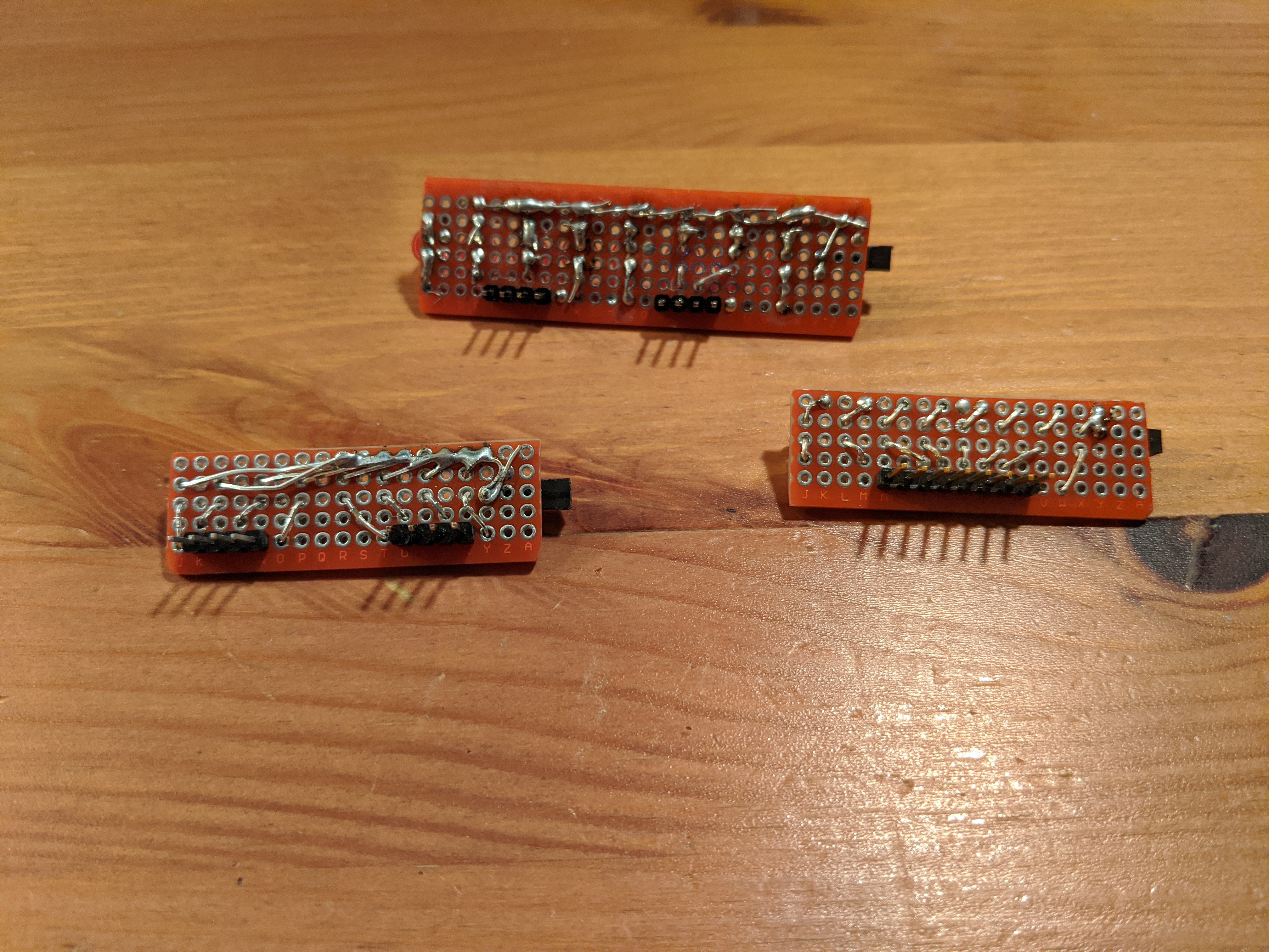
I thought I could solder a row of male headers to some protoboard and then add the eight LEDs and resistors. I’d need to add a female header on the side to connect it to ground. This felt like it was just about in my skill set, so I gave it a try.
I figured I’d make four of these for the three registers and the ALU. The first step was to cut the protoboard down to size and then sand the edges so they were no longer sharp.
I cut the first one by scoring it with a razor blade and then snapping the ends off and then filing it down by hand. It took a while but in the end I had a nice result. Too bad I didn’t account for all the space I needed so I cut that one too small 🙁. It was late so I tabled it for the next day when I needed to break out the Dremel for another project anyway. This time I quickly cut the ends with the Dremel and then used the tool to do a first pass on the filing. I still finished it up by hand, but it was much faster.
Turns out that the coaster my in-laws brought me back from a trip a few years ago is the perfect size to hold a PCB. I used that as a base and then filed the sides down to be nice and smooth.
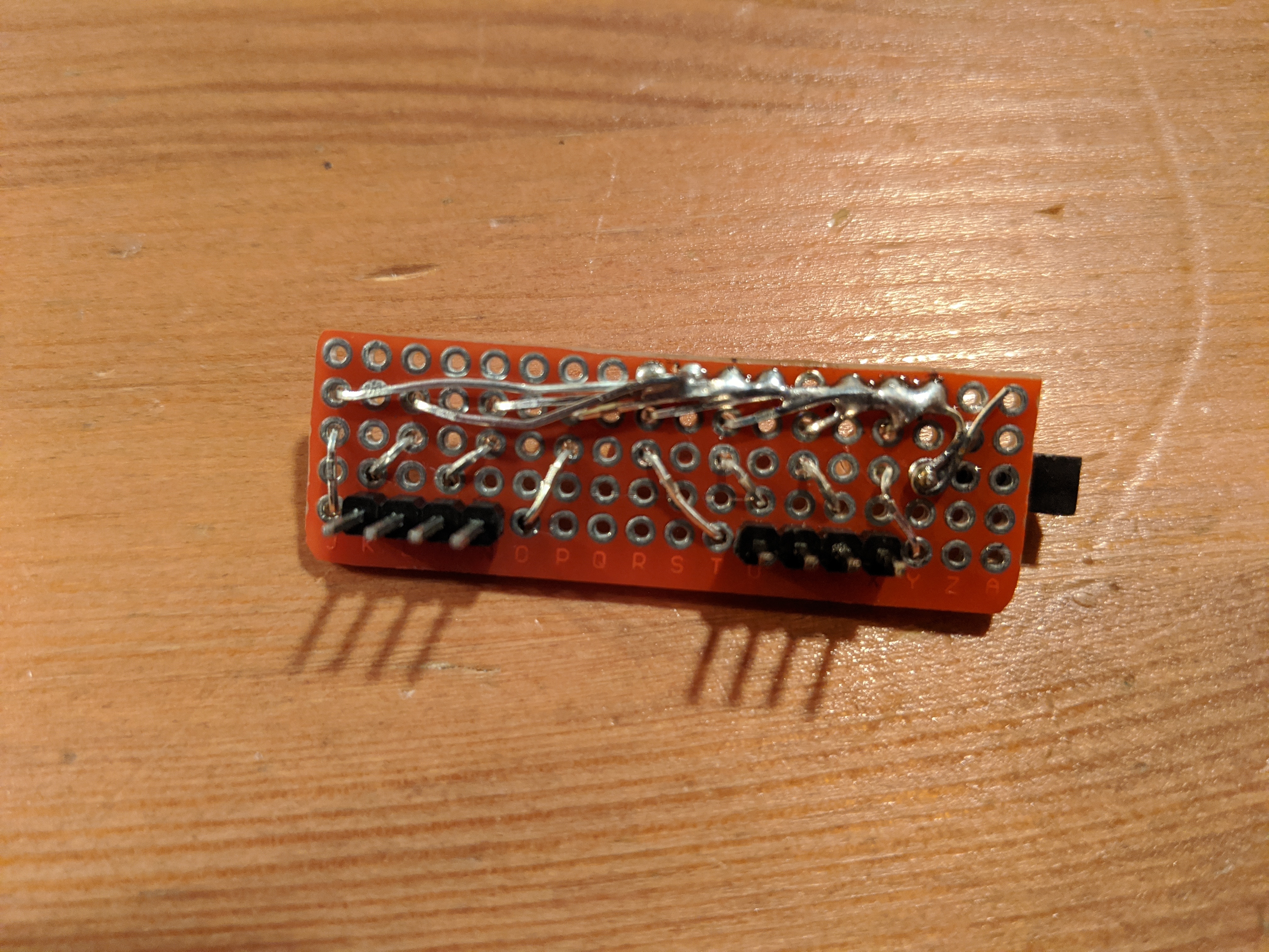
It took some trial and error to figure out the exact best way to solder everything in place. First I soldered two 4 pin male headers to the bottom of the board. They were spaced so they’d fit directly into the breadboard and connect to the registers.
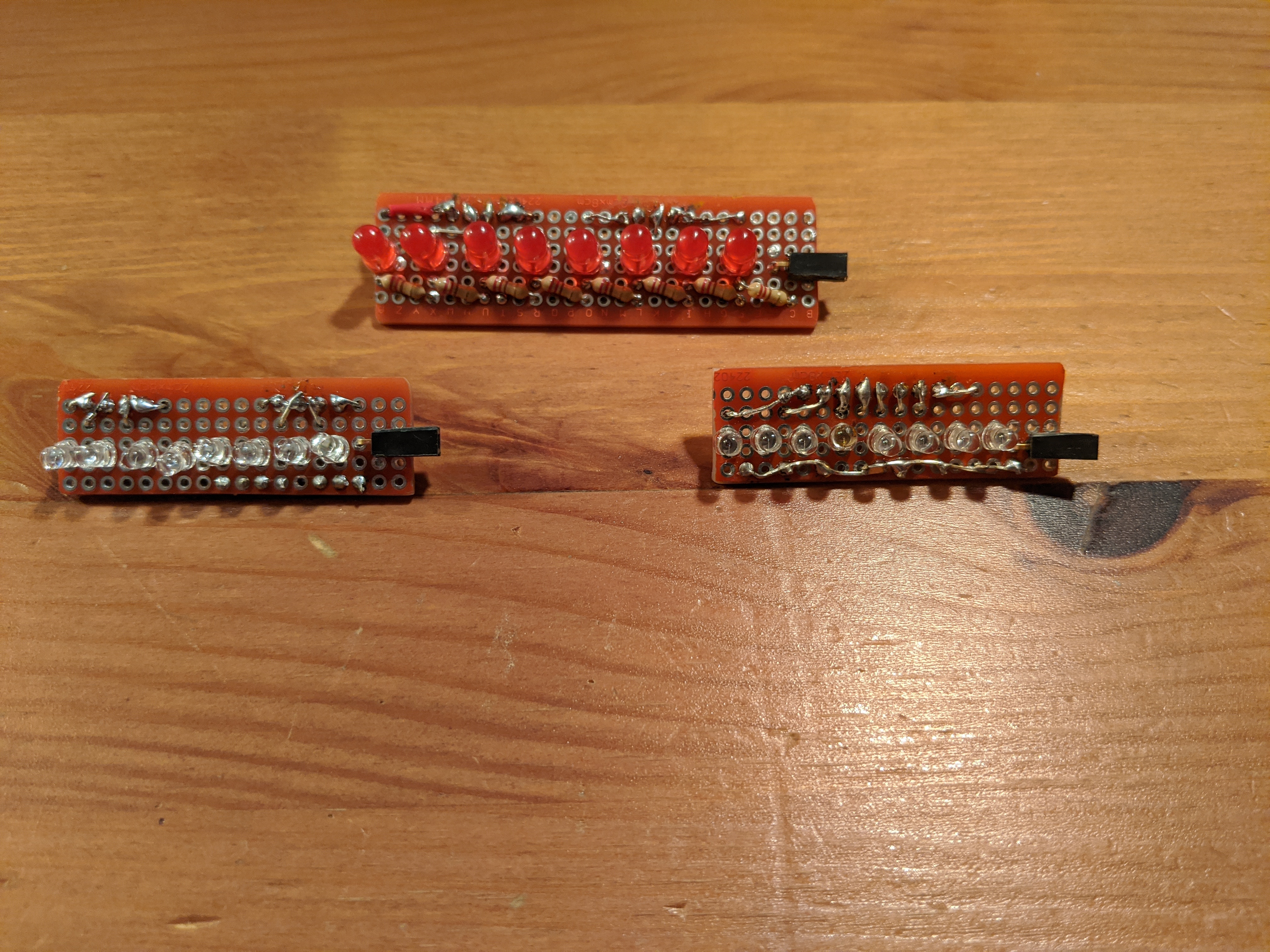
Next I placed the LED on the top of the board and bent the anode lead back up through the board to solder to the top of header. This may have been easier if I had done it first and then soldered in the headers.
The cathode leads were then soldered to a resistor that was placed at an angle behind it. The angle allowed me to line up all of the resistors and just solder them together in a line leading to the female header on the end.
This mostly worked (I had a bad LED in the middle I had to swap out) but took me all day to do the soldering and testing for one LED strip. I could probably do the second strip a little faster now that I worked out some of the kinks. Instead of tackling that project, the next day I woke up and bought a few packs of LED’s with resistors built in. This would at least let me make progress in my tests without having to solder everything first. And maybe I can come up with a better plan.
I bought two types of LEDs. One kind has the resistor directly in the housing. I bought the mixed bag of colors as well as another hundred each of the reds and blues. These are 3mm instead of the 5mm ones I already had. Worst case scenario, I can work them into the same type of LED strip but have it take up less space and not have to solder in an additional resistor. The other type has the resistor soldered to the anode lead in a long wire. I got the mix pack for these as well, twenty each of white, red, blue, green, orange, and yellow. To simplify testing, I crimped Dupont connectors to the ends of a bunch of these in groups of four.
And with that, I was able to test all of the registers and bus at the same time.
I recently picked up Ben Eater’s 8-bit computer kit.
The entire walk through for Ben’s computer can be found on
youtube.
The idea is to build a fully functioning 8-bit computer entirely on a
breadboard. This should be a great learning experience for me considering I’ve
never built anything particularly complicated in electronics. The first step is
to create the clock module that powers the rest of the computer. The clock he’s
designed has some interesting features
Speed control using a potentiometer
Step through mode - the clock advances when you manually press a button
A circuit to switch between these two modes
Halting the clock by setting the halt line high
This is step 1 of the clock module, the variable speed portion. It uses a 555
timer to produce the square wave that powers the LED. That LED is eventually
going to be removed from the board when the entire module is done, which is why
it hasn’t been cut down.
The clock kit comes with pre-cut jumper wires that you can use. The drawback to
them is that you can’t control the color for each length of wire. So I dug into
the second kit to pull out the spools of 25 foot colored wires. I figure if I
start with those wires now then the color coding will be consistent for the
entire project. Not only that, but the red wires will be the same shade for the
entire time.
That said, my biggest difficulty so far has been gettin’ gud at trimming the
breadboard wires. Ben’s computer winds up being very neat and orderly with the
wires. I’m hoping to get something close to that. I’ve tried breaking out my
calipers to start measuring every wire I cut. That’s helped a bit. I’ve also
tried bending the wires across the edge of the breadboard. I’ll keep it up and
jot down any more notes as I try new methods.
After several hours of practice, I think I have a system.
Cut a length of wire and strip some off the end (really doesn’t matter how much)
Use the bare part as a grip as you pull off the remainder of the insulation
Put the wire into the end of the breadboard, N-1 from the edge, where N is the number of breadboard holes you need the wire to travel.
Bend the wire down 90 degrees exactly where it comes out of the breadboard (this ensures you leave the exact right amount of bare wire to go into the breadboard)
Angle the rest of the wire going off the breadboard
Cut a piece of insulation the same length as the distance from where the wire is placed in the board to the end of the breadboard
Slip that insulation back on to the wire
Bend the remaining bare wire 90 down, using the edge of the board as a guide
Trim the excess wire just above the bottom of the breadboard
If you need a bunch of wires at once, measure out the right length past the edge of the breadboard and leave that piece of wire in. Then use that as the guide for other pieces you need to cut. There are eight holes at the bottom end of the board, so you can do eight wires pretty quick.
I used the above method to cut the wires for the rest of the work:
Today’s build was fun. It took most of the day (I really need to get better at
cutting wires to length), but I did a lot of other things in there like make
dinner and watch an episode of Better Call
Saul.
For all of the details on how this works, I recommend checking out Ben’s
youtube
videos. He goes into more details than I could.
Since we started working remote I’ve been asking my team 1 “Question of the
Day” during standup. I started by posing the question at the start of the
meeting, but have since switched to asking before the meeting. This gives
people some time to come up with better answers. I try to avoid asking for
“favorites” because that can put too much pressure on people to come up with
the right answer. So instead of “What’s your favorite movie?” (which is
definitely on the list) I’d ask “What’s a movie you’ve enjoyed recently?”
As a child, what did you want to be when you grew up?
As a kid, what was your go-to routine for a sick day?
Besides insects and spiders, what animals annoy you the most?
Best movie that would be improved if all characters were muppets except one. Name the non-muppet character.
Brewsters Millions: If you had to spend $10 M in one month, how would you do it? Like the movie, you can’t have anything to show for it at the end of the month.
Favorite Movie
Favorite Sci Fi
Favorite color to wear
Favorite lunch spot (when you were working in your most recent office)
Favorite lunch spot currently
Favorite quick service restaurant in NYC
Favorite restaurant in NYC
Favorite song in a genre you don’t normally like
Have you ever broken a bone or gotten a scar? How’d it happen?
How much wood COULD a woodchuck chuck if a woodchuck could chuck wood?
If someone made a movie of your life, what genre would it be?
If you could be a cartoon character for a week, who would you be?
If you could go back in time and pay more attention to any class in high school, what would you choose?
If you could have an actual spirit animal what would they be?
If you could have any job in the org for a week, what would it be?
If you could magically become fluent in any language, what would it be?
If you could meet any historical figure, who would you choose and why?
If you could meet any living person for dinner, who would you pick and why?
If you could pick up a new skill in an instant what would it be?
If you could shop for free at one store, which one would you choose?
If you could start a charity, what would it be for?
If you had a personal assistant, what would be the first thing you ask them to do?
If you had to perform on a talent show, what would you do?
If you had to teach a class, what class would it be?
If you left your current life behind and ran away to follow your dreams, what would you be doing?
If you were a wrestler what would be your entrance theme song?
Name a brand you are loyal to
Name a fun historical fact.
Name a toy you enjoyed playing with as a kid.
Name one thing that was on your bucket list that you’ve done
What are you kind of snobby about?
What band would you travel back in time to see?
What book have you read lately (it’s been a while since the last time this was asked, maybe you’ve read a new thing since then?)
What celebrities have you met?
What class would you want to take?
What country is on your bucket list to visit?
What do you look forward to about getting older?
What fictional family would you be a member of?
What have you done your entire life but are still bad at
What hobby would be a lot of fun to get into?
What household chore do enjoy the most?
What ice cream flavor do you like?
What is the best fruit?
What is the best piece of advice you’ve received?
What is the most useless thing on your desk right now?
What is the weirdest food combination you’ve made and tried?
What is the worst fruit?
What is your biggest pet peeve?
What is your cellphone wallpaper?
What is your favorite childhood vacation?
What is your favorite family tradition?
What is your favorite holiday and why?
What is your favorite magical or mythological animal?
What is your favorite or memorable childhood vacation?
What is your favorite sport to watch? If you don’t like watching sports, take the question as broadly as possible.
What movie have you seen lately (it’s been a while since the last time this was asked, maybe you’ve read a new thing since then?)
What music do you put on when you want to get pumped?
What song do you hate and have to turn off the radio when it comes on?
What subjects should be taught in school but aren’t?
What superpower would you want?
What teacher did you have that you didn’t like? Why?
What topic could you give a 20-minute presentation on without any preparation?
What was a notable costume (maybe for Halloween) you had growing up or later?
What was something you thought would be easy until you tried it?
What was something you thought would be hard until you tried it?
What was the first album/tape/cd/mp3 you bought?
What was the name of the street you grew up on?
What was the worst job you ever had?
What was your favorite game to play when you were a kid?
What was your worst haircut experience?
What works of art have really made an impression on you?
What would the title of your autobiography be?
What would you change if you were CEO?
What would you do if you were invisible for a day?
What’s a book you enjoyed as a kid?
What’s a movie you enjoyed as a kid?
What’s a work (not necessarily here) achievement that you are proud of?
What’s the first thing you do when you get home from a trip?
What’s the most beautiful place you’ve ever been?
What’s your “goto” joke?
What’s your favorite Summer Olympics sport?
What’s your favorite baked good?
What’s your favorite cheese?
What’s your favorite dessert?
What’s your favorite smell?
What’s your favorite sport to play (as usual for sporting questions, please interpret the term “sport” as broadly as you need in order to answer the question)
What’s your go-to diner order?
What’s your perfect sandwich?
What’s the best or worst prank you’ve played on someone?
What’s the most outdated piece of tech you still use regularly?
What’s your drink of choice? (Either alcoholic or non.)
When did you like the movie more than the book?
When you’re having a bad day, what do you do to make yourself feel better?
Where’s the most surreal area you been to?
Where’s your favorite place to nap?
Which celebrity chef would you like to fix you a meal?
Who is one of your favorite (living) musicians?
Who is your favorite athlete?
Who was your favorite teacher?
Who would play you in a movie of your life?
You have a week to spend in a place you’ve never been before (travel not included), where do you go?
You have to sing karaoke, what song do you pick?
You have your own late night talk show, who do you invite as your first guest?
Updates:
Updated 8/18/2020 with 20 more questions!
Update 6/3/2021 I added more questions in a follow up post
I’ve been working on a project to create a Bluetooth “keyboard” with arcade
buttons as the switches. Of course I want the buttons to light up. And I’d like
to do this without using too many pins on my microcontroller. Naively if I had
ten buttons (which I do) that would be 20 pins for the buttons and LED’s. The
board I’m using has 21 pins. So that’s
doable, but then doesn’t leave room for a lot of expansion (I also want a
volume knob for instance…).
Button Matrix
The solution I looked at was well documented around the web. I mostly used this
sample from
Adafruit since
I was looking for examples using CircuitPython. I used a pair of Adafruit’s
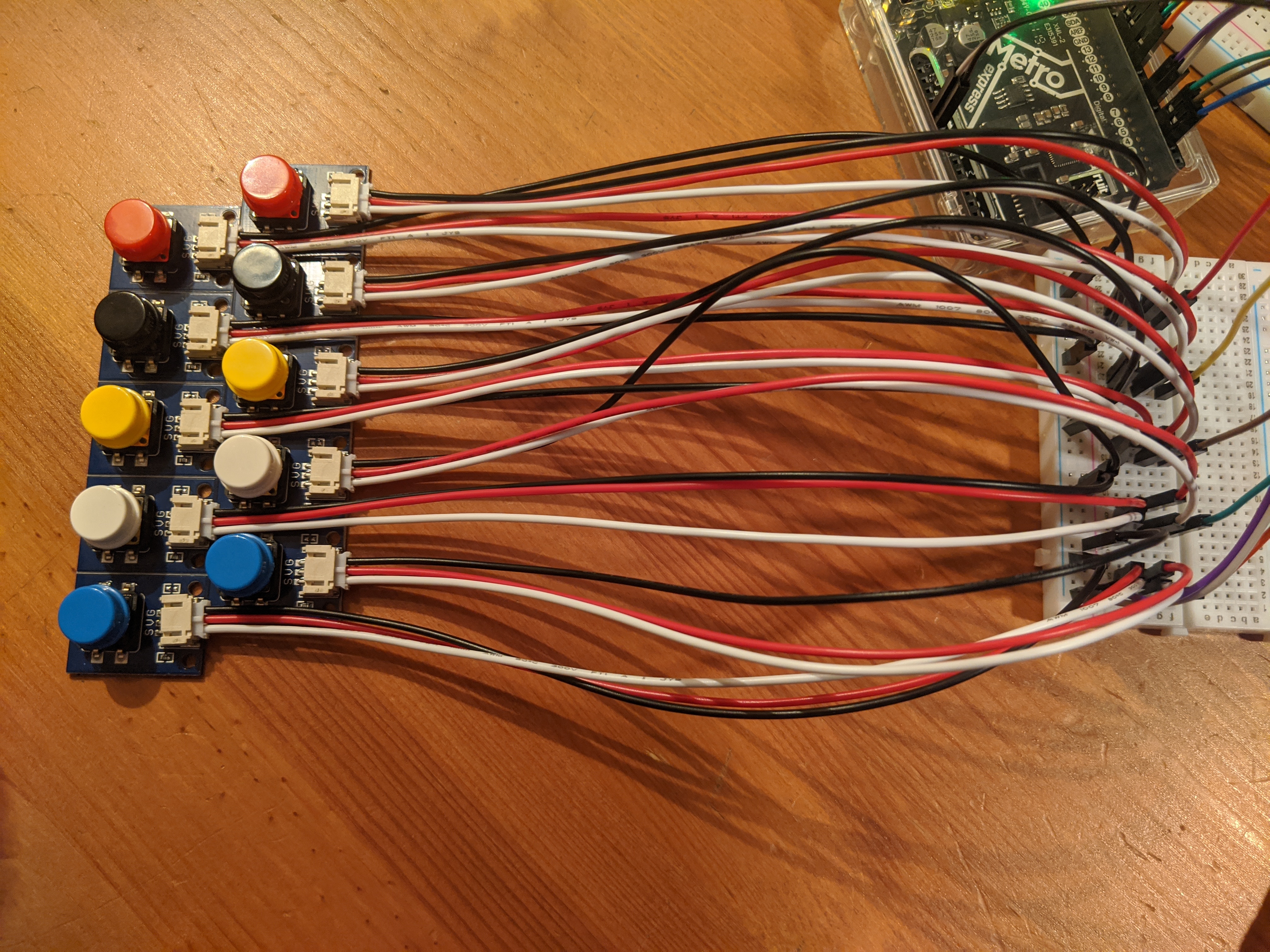
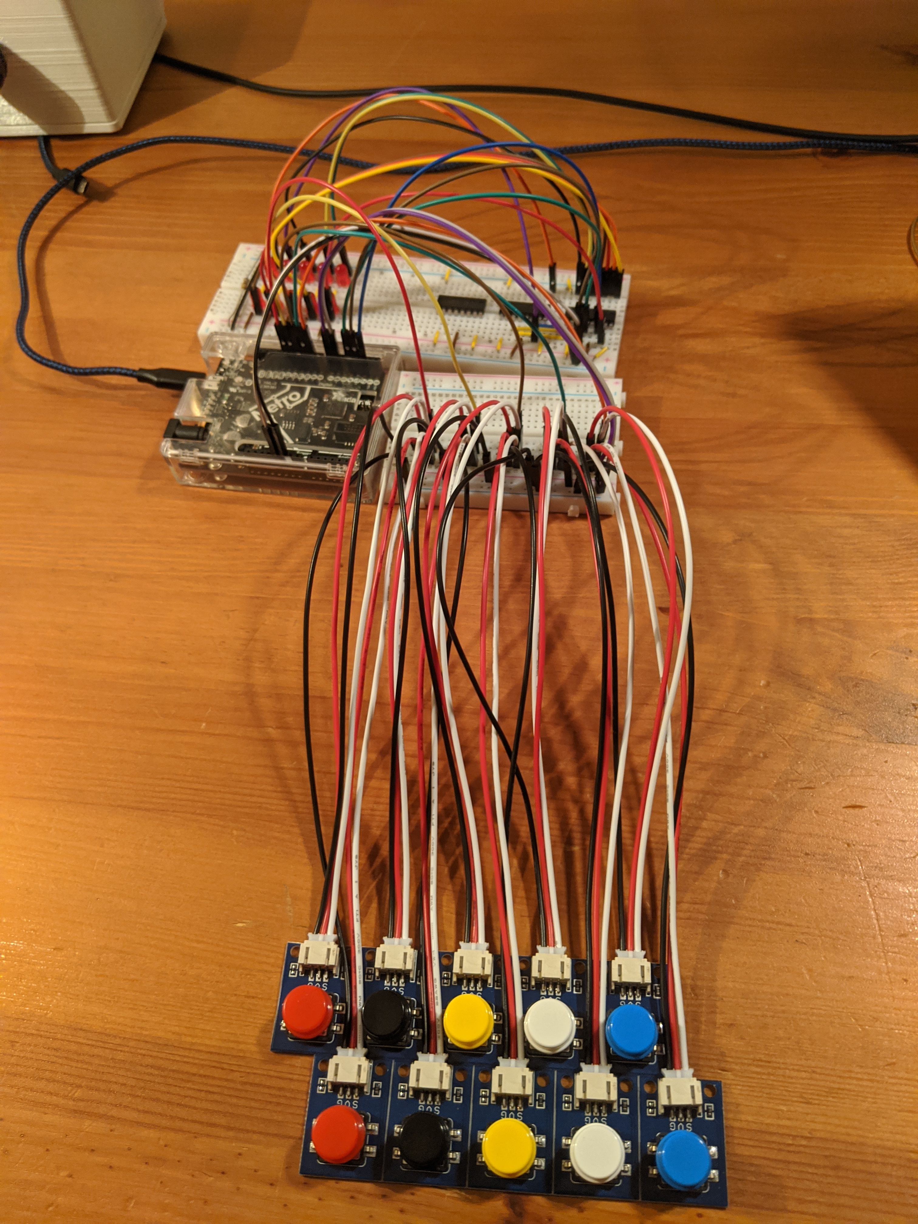
STEMMA wired buttonsto wire this up.
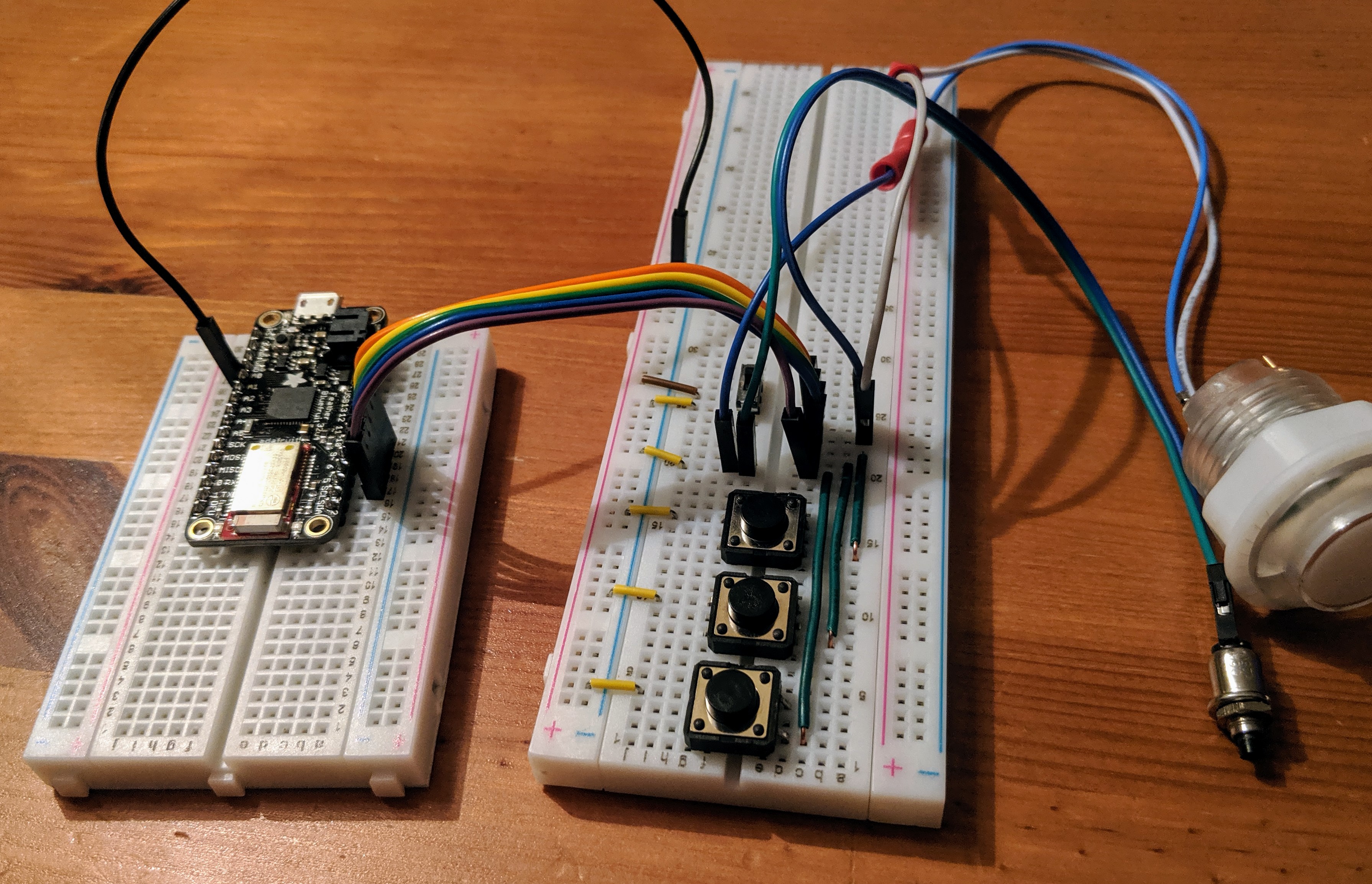
The two rows of five colored buttons mimicked my real world project so it
helped to visualize what I was doing. Each button has a 3 wire JST connection
coming out of it with a white, black, and red wire. The white and black wires
form a circuit when the button is pressed. For each board of five wires (my
row), I connected all the black wires to the ground rail on a breadboard to
wire them together (the rail wasn’t connected to ground). The other board was
wired to the other power rail. For my columns, I just paired up each of the
colors (the two blues, the two whites, etc). I plugged their corresponding
white wires to a row on the breadboard. I believe that the red button is
intended to be wired to a pull-up resistor which I didn’t need for this project.
Just so they wouldn’t be in the way, I wired them up similar to the white
wires.
Then to connect to the board, I plugged the two rows (the power rails) to pins
6 and 7 of my board. The columns were plugged into 9, 10, 11, 12, 13. I
pulled sample code from the Adafruit site and tweaked it to my configuration (2
rows instead of 4, 5 columns instead of 3, pin numbers, etc). The
adafruit_matrixkeypad library does most (all) of the heavy lifting here.
Whenever I pressed any button, it would show up as if
the corresponding button on the next row was also pressed. After some hand
wringing and checking all of my connections I realized that my breadboard
actually has a short across those power rails. After pulling out all of the
connections, rotating the board, and trying again, it worked just fine.
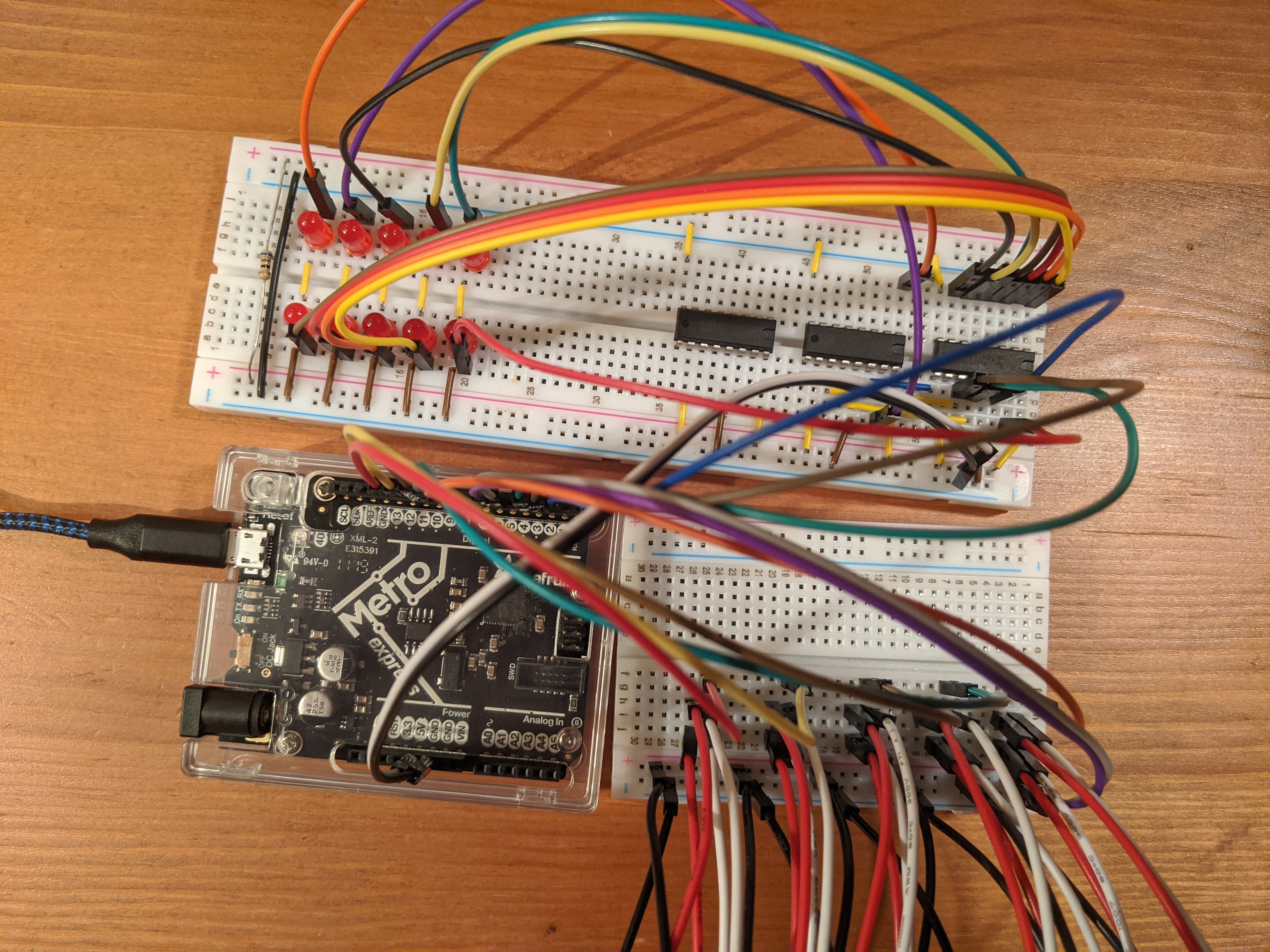
IC the Lights
Next I needed to get the lights working. I knew you easily create
this type of output using shift registers. And as it happens I have
about a dozen of
74HC595’s
kicking around in a drawer. Problem is, I had no clue how to use
them. I got lucky with some articles I happened to stumbled upon
that had an example. Page 98 (according to the PDF, it’s 111 if
you’re using the numbers on the bottom of page) of the Experiments
Guide for
Metrohas an article about adding “More LED’s”. That’s a good start for
the wiring up. Only two problems.
The sample code is in C not CircuitPython
I want 10 LED’s not 8
Instead of figuring things out from scratch, I did a little googling and came
across nuke66’s
project
which was pretty much exactly what I needed. Again, all I had to do was change
the pins to what I had. The sample pretty much just toggled everything on or
off. Controlling all of the lights at the same time is pretty easy, so why not
something more fun? Let’s create a binary timer. Count from 1 to 256 (2 raised
to the 8th) using the LED’s as outputs. So I made (minimal) changes to code.
Sadly, I didn’t think to take a video of this marvel of modern electronics.
importtimeimportdigitalioimportboardimportsimpleiodata=digitalio.DigitalInOut(board.D2)data.direction=digitalio.Direction.OUTPUTlatch=digitalio.DigitalInOut(board.D4)latch.direction=digitalio.Direction.OUTPUTclk=digitalio.DigitalInOut(board.D3)clk.direction=digitalio.Direction.OUTPUTdata=0whileTrue:data+=1if(data==256):data=0# write to 595 chip
latch.value=Falsesimpleio.shift_out(data,clk,data)print("sending: {0:#010b} {0}".format(data),end="\n")latch.value=Truetime.sleep(0.1)
Next up: light them up based on which button is pressed. The button matrix already allows you to attach data to the button object which you get back when you query what’s been pressed. Instead of a meaningless label, why not just put in the id of the LED? Numbering each LED with a power of two will let me simply add up the keys pressed and send that out to shift register.
That works except for the last two buttons which are greater than the default 8
bit limit of simpleio.shift_out. How do I wire in those two LEDs? I could
just wire in a second shift register with 3 more wires but that would be more
wires than it would take to just wire in two more LED’s, make the code more
complicated, and be really dumb.
The designers of the 595 agree with me. As it turns out, you can daisy chain
multiple chips together. The bad news: I have no idea how to approach that.
After some more google I found a bunch of videos that were helpful in that they
showed what I wanted to do, but unhelpful in that it was a mess of wires and
not clear what they were doing. OK, videos out. Guess I’ll have to read to get
the answer here.
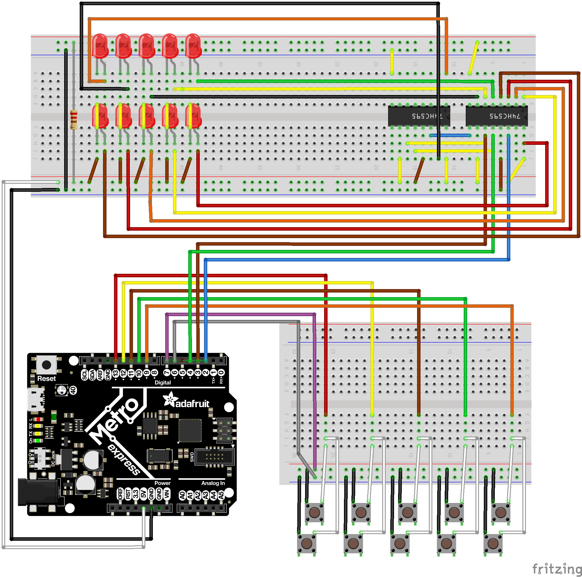
Mostly I was looking for a good diagram, which is what I found on
protostack.
Following this I saw that all I needed to do was:
Connect pin 9 from the first shift register to pin 14 of the second one
Connect pin 11 on both chips together
Connect pin 12 on both chips together
I had started off on a half size breadboard so I needed to tear down everything
I had to make room for the new chip and LED’s. In doing so I forgot to tie the
OE (output enabled) to ground. This had some annoying and confusing results.
Essentially the output would flicker because nothing was telling it whether to
be on or off. The output would be more reliable if I held some of the wires
(which really confused me). This reminded me of last time when I forgot to
include a pull-up resistor in a button. I’d like to say that’s how I discovered
the problem. But no, I went the classic route of taking it apart again and
redoing all of the connections. I realized I didn’t have enough wires to
connect the pins to ground and that’s what I had forgot.
Now that I had everything wired correctly, I still needed to figure out how to
control the additional input. If I tried sending anything higher than 255 I was
still not getting my new LED’s to light up. Reading through the CircuitPython
doco,
I saw that the shift_out function has a default paramter of bitcount set to
Well… I want 16 bits. Setting that parameter worked.
In my last go round I spent a lot of time mucking about with C++ to get things
working. While searching through the Adafruit
site, I came across a newer Bluetooth friendly
device, this one capable of running
CircuitPython. There’s even a tutorial for
turning it into a Bluetooth
keyboard.
So I bought two. Due to Covid and the fact that Adafruit is focusing on
producing PPE, it took an extra week or so to arrive. I got them this week and
immediately started playing.
CircuitPython
CircuitPython is a version of Python that will run on a whole bunch of
boards. Anything in the Adafruit line
that is “Express” seems to be able to run it. Some Arduino boards support it as
well.
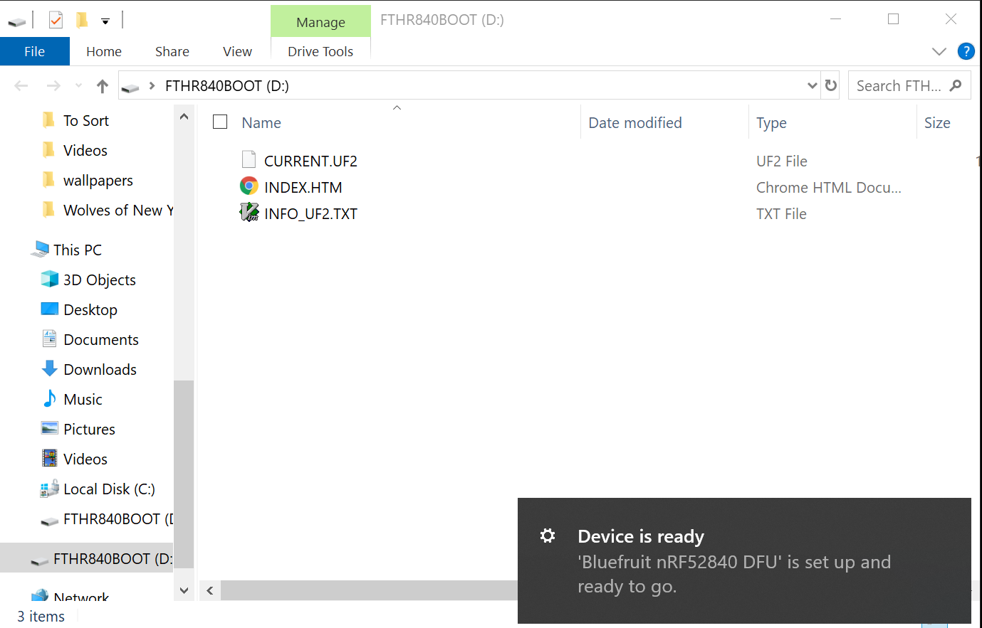
Installation is pretty trivial on the Feather Express I got. The Adafruit site
has a pretty thorough
explanation.
Pretty simply though, you plug it in to your computer. It will install itself
and then automatically present itself as a file system.
When that happens, go to the CircuitPython download
site, download the installation for your
board, and then drop that into the new folder. The board will restart and now
the root folder will have code.py. Write your python there. Whenever you save
it will automatically reload and run that script.
Hello World
The Hello World app is pretty easy (in fact it’s what comes in code.py by
default.
print("Hello World")
That’s it. This will just print “Hello World” to the serial bus. You see it by
opening up the serial port and watching it. While you can use the Serial
Monitor from the Arduino IDE, it’d be nice to no longer need that tool at all.
Luckily, PuTTY can handle serial ports as well as SSH. First you need to figure
out what port the device is connected to. If you have multiple devices they’ll
all connect to a different port, even if they aren’t plugged in at the same
time. Which is convenient since you can mentally associate a different port
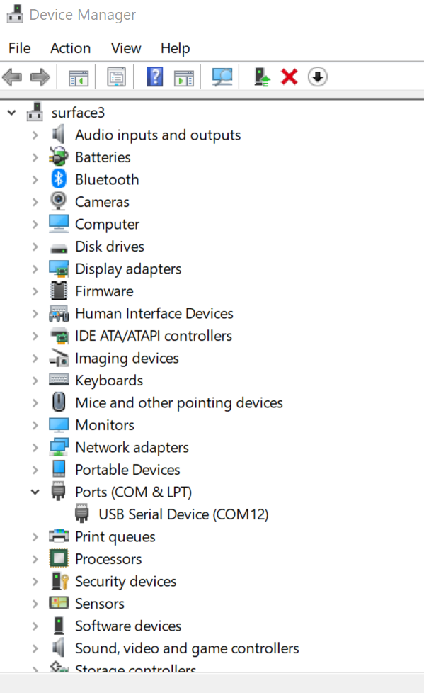
with each device. To determine which port it’s using open up the Device Manager
and expand the Ports (COM & LPT) node. It will be listed there. In my case,
it was port 12.
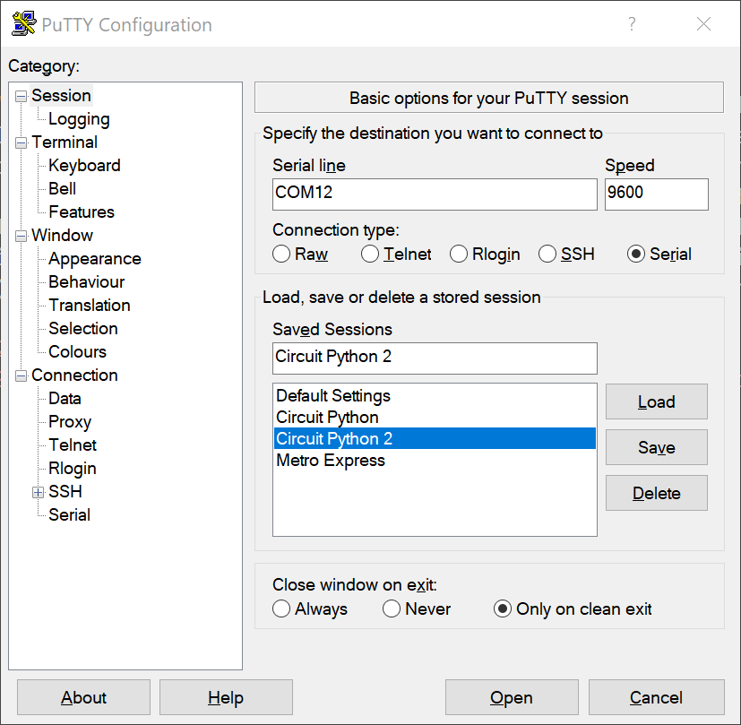
Fire up PuTTY, select the serial radio button, and enter COM12 in the
address bar. I left the speed at 9600 and it worked fine. Press connect and
you’re now connected to the console output of your board. You may need to
restart the program (just save it again).
I had some issues using vim, which was disappointing. Saving wouldn’t trigger a
restart. I moved to Visual Studio Code. My preferred way to work is actually
with both tools running, using VS Code for most editing tasks and switching to
vim for specific types of edits. This actually works out pretty well. The only
hiccup is that after saving in vim, I need to switch to VS Code and save it
again if I want the code to run. It seems that the interpreter tries to
evaluate the code before vim is done saving it.
Another nice touch is that any syntax or runtime errors automatically go to the
serial output. For example, if you try to call a function that doesn’t exist, the board
will stop evaluating and just dump the error out. Since you may not be looking
at the serial output all the time, the board will flash it’s lights so you know
there’s an error.
Back to the Box
Seeing as I already had a working set of buttons implemented in C++ on my
button box, I wanted to try and rewrite that code in Python. It took me a
couple of nights (and some frustration) to get it working in C++. On the other
hand, it was about an hour or so to rewrite it all in Python. I had a couple of
things going for me.
I had better examples (including
nearly
exactly what I
wanted)
in CircuitPython
I already compiled a list of all keystrokes I wanted to be able to perform
Adafruit has put together a great set of libraries that makes the tasks I
was looking to perform really easy
In addition to that, the feedback loop is super fast in CircuitPython. Write
code. Save. Debug. Repeat. No compiling, no lengthy deploy process since it’s
just a small script.
So not only was I able to bang out the code to get me back to where I was
pretty easily, I was able to add the code to turn the rotary encoder (spinning
knob) that was already on the box into a volume knob.
Today’s pull
request
has a bunch of files in it, but mostly because I checked in the python
dependencies I need in order to get. I also included a couple of scripts that
I wrote to just test specific things in isolation (like buttons or the rotary
encoder).
Hardware
The hardware side was a little trickier. First, these boards don’t come with
the headers attached. So I had to solder them myself. This is normally a scary
point for me, but because of another project I had been working on, I was a
little more confident going in. In fact I took this as an opportunity to solder
a bunch of headers on a variety of boards I had lying around. This went pretty
well (no shorts!) and didn’t take too long. I made some mistakes, but was able
to fix them all.
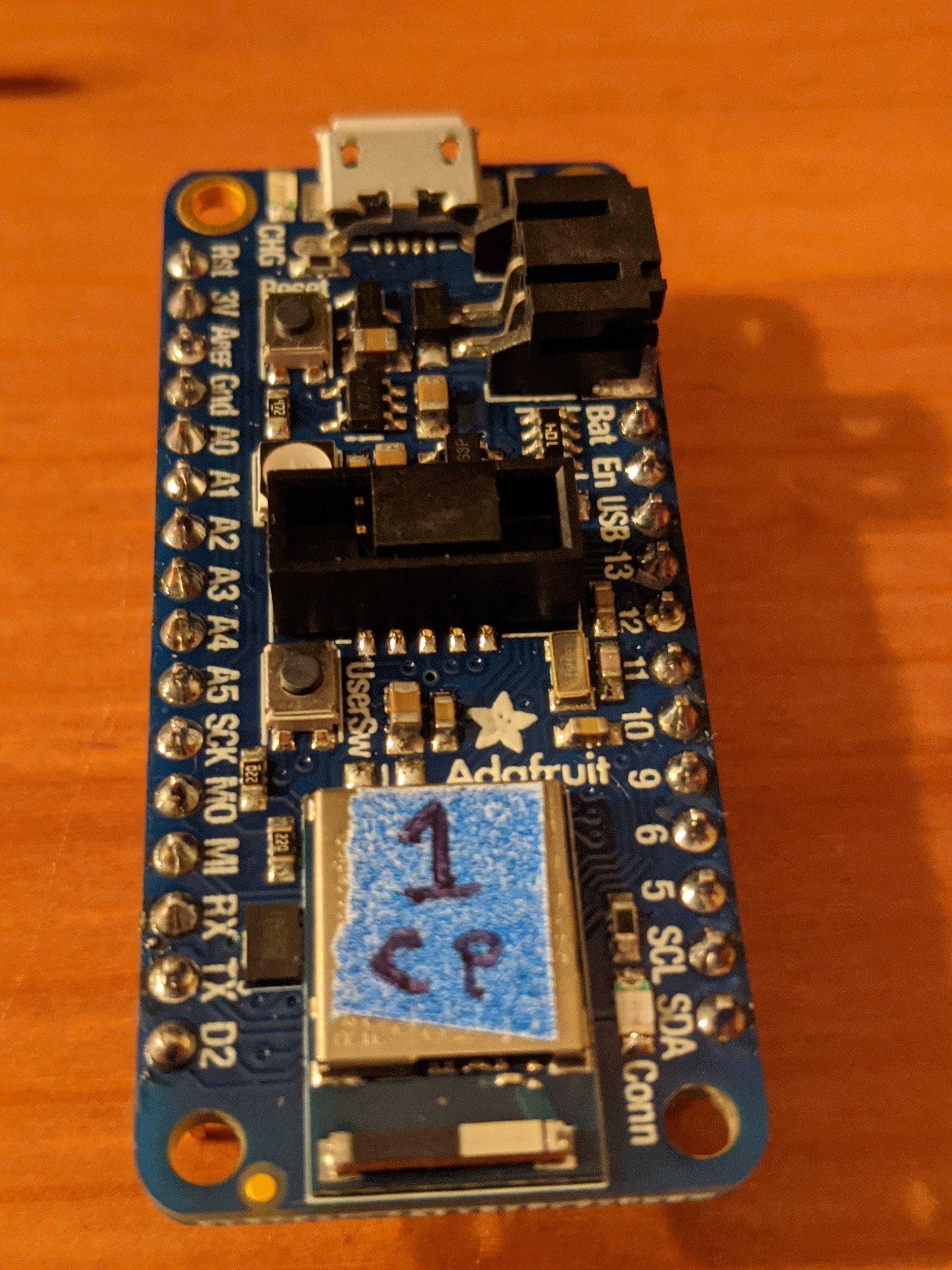
This is what the board looked like when I was done. The blue sticker is there to differentiate it from other types of boards (which have another color sticker) and my other board of the same type (which has a different number written on it)
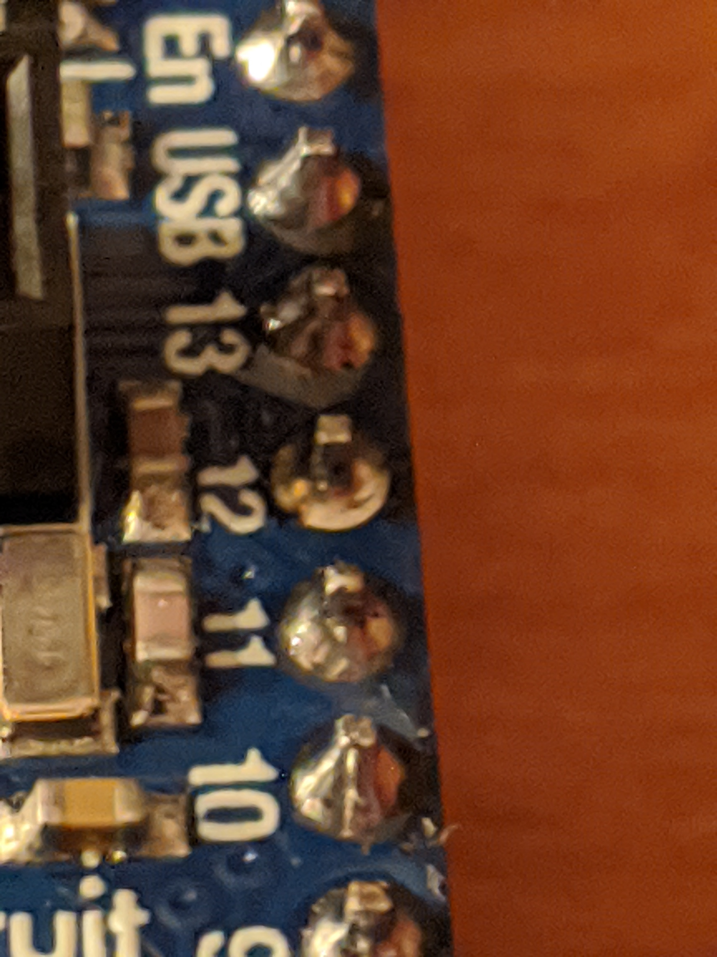
And here’s a close up of the soldering work.
My next problem was that the buttons seemed to be firing presses pretty
sporadically. After about half an hour of frustrated debugging, I realized that
the sample code I was using wasn’t explicitly setting the buttons to use a
pull-up resistor. Adding the line button_top_red.pull = Pull.UP for each
button fixed that! There was another way to handle this, plugging a third wire
from the button to the 3.3v pin on the board. The STEMMA
buttons I have for breadboarding do
have a third wire, and I was able to confirm that plugging it into power would
fix the issue. The reason I prefer the pull-up resistor solution was because I
have no idea where I’d attach a third wire to the buttons I have. This is a
hole in my understanding how buttons work. I’m fine with it for now, but will
need to figure this out at some point.
At this point, I was at parity with what I had before but I really wanted a
volume knob. I found that I would absentmindedly spin the knob on the box even
though I knew it didn’t do anything. I really wanted it to work. The code was
easy, and it was easy to test with my breadboard friendly rotary encoder that I
had. But the one I had in my box didn’t have the easy to attach to header pins.
So I grabbed a piece of protoboard, cut it down to size a bit, and soldered the
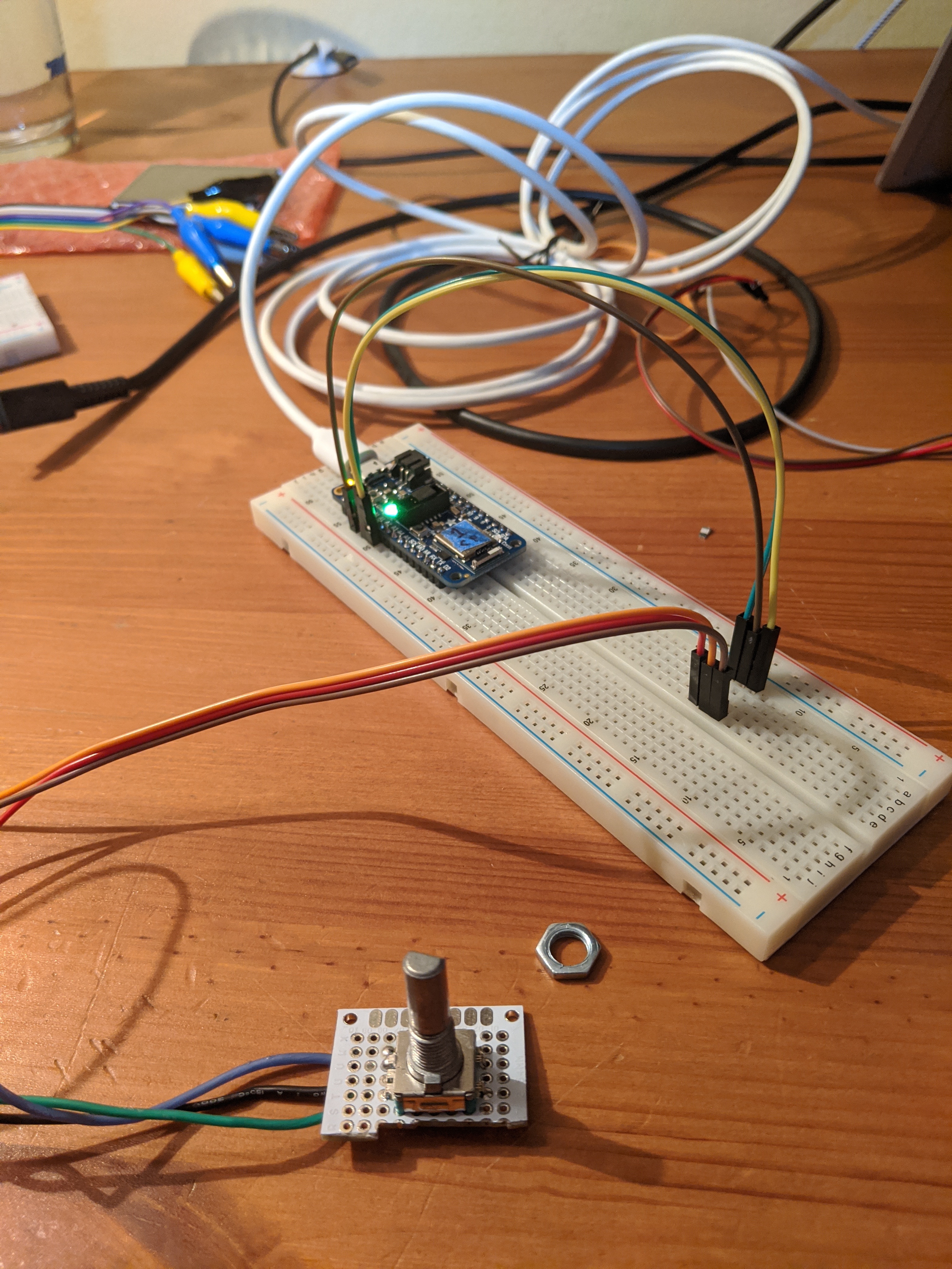
encoder to it along with some wires.
This is what it looks like from the top (and plugged into a breadboard for testing)
Conclusion
It was a really busy day, but much more productive than I have been in the
past. Between the speed of developing with CircuitPython and confidence built
up with the electronics aspects, I was able to take on more than I normally
would and be confident that I would finish everything.
With all of the Zoom meetings and working from home, I decided to tackle the task of configuring my buttons project to be able to control Zoom. The big things I wanted were:
Start a new Zoom meeting
Mute/unmute
Enable/disable video
Close my Zoom meeting (I hate fumbling with the UI and clicking multiple buttons on the screen to get out of a meeting)
Share screen
Zoom has a list of shortcuts on their site. Most of what I want are easy key combos. For example, starting a meeting is command + control + v. Some of them were a bit more complicated though. Closing a Zoom meeting or sharing a screen both have shortcuts, but the shortcuts bring up a dialog box. Having to click more buttons on my keyboard or with mouse defeats the purpose of dedicated hardware buttons. Luckily, both of those situations have pretty standard flows. Closing a Zoom maps to command + w followed by enter. Sharing maps to command + shift + s then right arrow and then finally enter.
Refactor
Basically I need to be able to support chords. This will take a refactor. As it
stood, the code just had a giant switch block (really lots of if’s) that
figured out which key set to send. Now I need to be able to send multiple keys
per button press. It’s high time I create a command class. For lack of a better
name, I’ll call it QuinCommand. It can take up to five different key
combinations that it will play out in order. (get it? “quin”… okay so it’s my
name too. It works on multiple levels.) It will need to be able to send out
Bluetooth commands, so we’ll need to abstract that out to a dedicated class
too. Sticking with my theme of picking bad names, that’ll be called Blue.
This cleans up a lot of my main file. All that that’s left is to pull out all
of the constants that define the specific key combos and comments that describe
them and where to get more info on creating more. That was a lot of code that
gets moved to CommandsConstants (probably the best name of the bunch…).
With all of this cleanup done a couple of things stood out at me. First,
there’s still a lot of boilerplate code that I’m no longer using. Delete it.
Second, there’s a whole sub-folder of code kicking around that was copy and
pasted of this project. It confuses me whenever I open up the project. Delete
that too.
Much better.
Relearning C++
It’s been ~20 years since I’ve seriously written any C++. And that was high
school. So this entire refactor took a lot of googling. How to make classes,
how to define a header file in such a way that you can include it multiple
times. How to handle arrays or strings. That last bit kicked my ass quite a
bit. I’d like to say I researched and figured out the right way to do things.
But no, I just stack overflowed (the site) for a bit tried a bunch of things
until something worked. I’m 💯 percent sure that it’s not the best answer. I’m
trying to send constant length constant strings around, there has to be a way
to do that without resorting to a memcpy. At the end of the day (and it
really was the end of the day when I was working on this – I was tired) I
went with a cludge that worked.
Wrapping up
I’d like to change the commanding architecture to be based off of an interface
(or an abstract class with all virtual methods… cuz C++) and have completely
custom logic for what happens when each command is invoked. It’d also be nice
to wrap the command in a button class that tracks the state of the button press
and handles whether or not to resend a command if I haven’t taken my finger off
the button yet. Realistically, that’s probably not going to happen for a long
while. The box works well enough for now and I have a couple of new
boards on order that run python. So
it’s likely that I’ll be porting this over to that, which should have a faster
development feedback loop for me.
Writing all of this C++ really made me miss the simplicity of C#.
I’ve finally taken the time to configure Windows
Terminal.
I’ve been a big fan of ConEmu in the past. It has
tons of configurable settings and features. But honestly, I switched to it for
the easier copy/pasting in the command line. Since the new Windows Terminal
can do that, then I thought it would be worth giving a shot.
Below is my current configuration after about an hour of reading docs and
fiddling. I like that I was easily able to find the Desert
theme (which is what I’ve been using for
vim for over a decade now).
Interesting tidbits I stumbled across while reading the docs
Holding alt while opening the settings will open the default settings
Pressing any arrow key while holding alt will jump to the pane in that
direction.
Pressing any arrow key while holding alt-shift will resize current the pane
in that direction
Settings are reloaded as soon as you save the settings file. No need to
reload tabs. This confused me while I was trying out different color schemes
Chrome-style shortcuts work for zooming in/out in a pane
Aero doesn’t work on my Surface3 🙀
Wishlist
It would be nice to be able to click on links in the console and have them open
in my browse. There’s an
issue open for that, so
hopefully it makes it into an upcoming version.
Another ConEmu feature that I would love to see is the ability to open up a
tab as an administrator The
current workaround is to Ctrl+Shift+click on the icon in the taskbar to open
a dedicated admin prompt. This is a bit more work than I’m used to, but most of
what I’m adminning about for is to just run
Chocolatey. I can make due.
It’s been a while since I’ve worked on my Arduino project to create a Bluetooth
keyboard. In that time I have been using my keyboard a little bit, but it needs
some work, ranging from small tweaks to major overhauls. This post is to remind
me how to do the small tweaks. Some of it will be very specific to my current
setup.
The first thing I’m remembering, and this sounds really dumb but I had to
relearn it, was that the Arduino needs to be on. I had assumed that merely
plugging it into my laptop would have been enough, but nope. Fully powered on.
Check. ✔
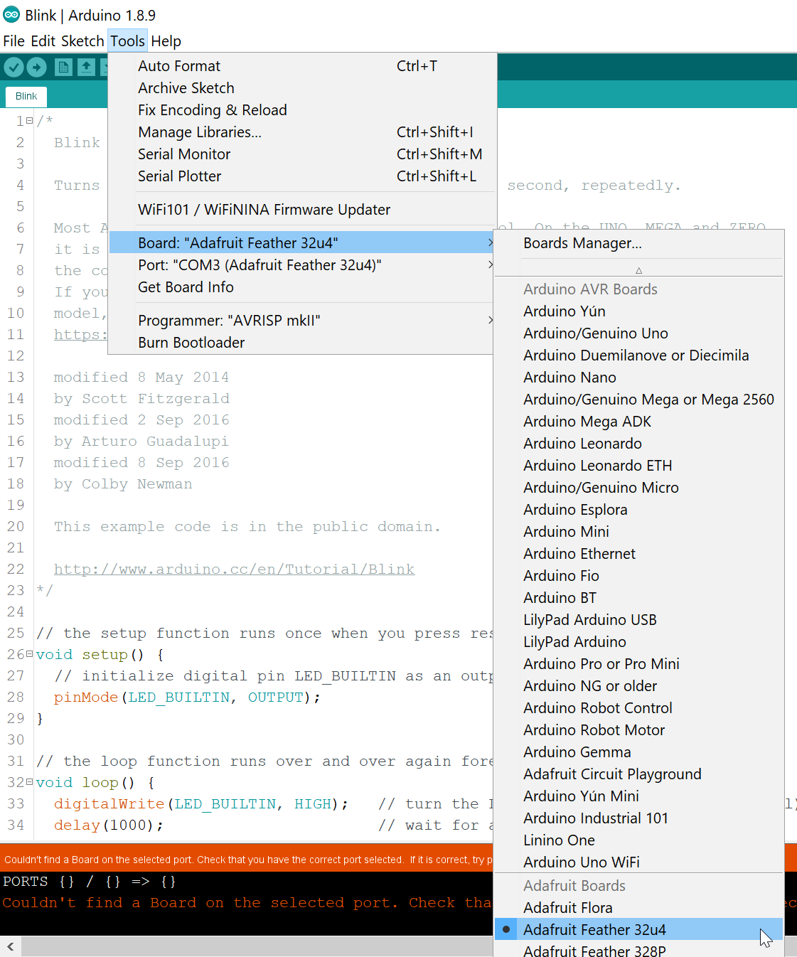
Now that the board is on, we can verify all of the settings in Arduino IDE,
including making sure the correct board is selected and the correct com port is
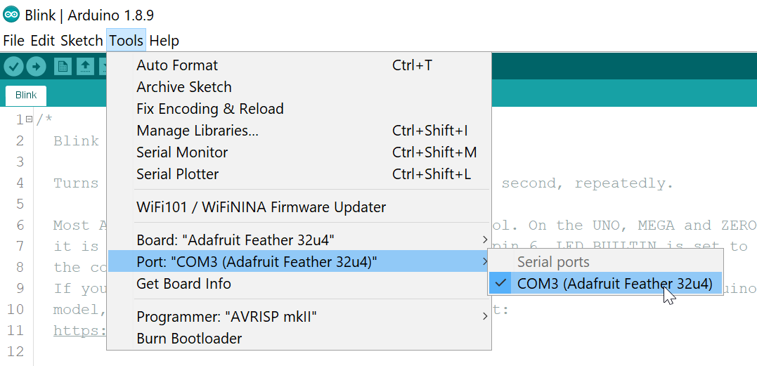
being used. For my setup Adafruit Feather 32u4 and COM3 are the expected
values.
Select Board
Select COM Port
Now that the board is connected, to view debug output while it’s running you
can open up the Serial Monitor with Ctrl-Shift-M.
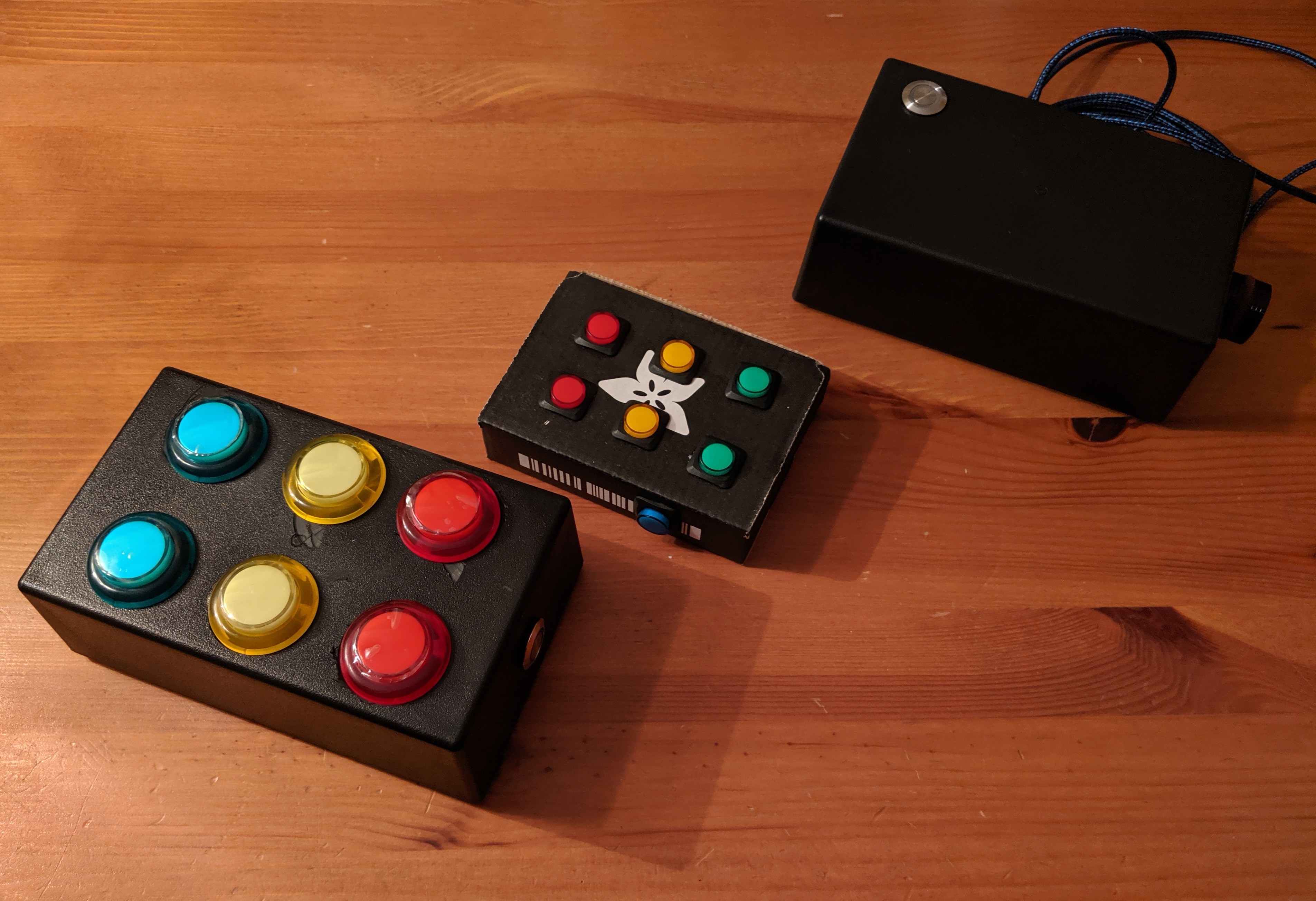
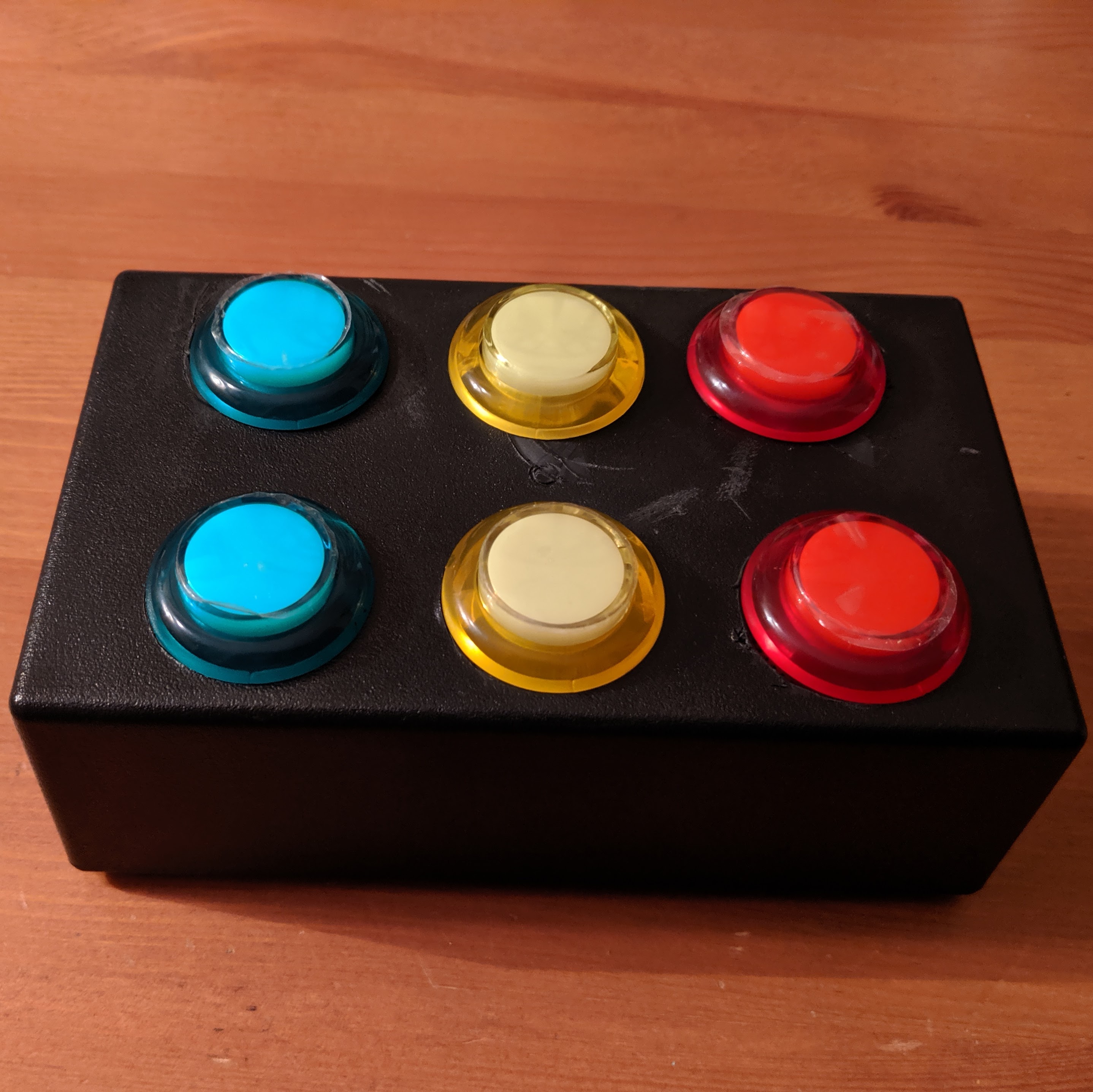
Today I was able to complete the first fully working prototype of my keyboard.
It has 6 16mm arcade buttons – two each of green, yellow, and red – runs on a
350mAh lithium ion battery, and is
completly wireless. It doesn’t even have a wire to charge it since I didn’t
have enough space to mount the port in the case.
Build It
Mostly today was a build day. I had most of the code in place, so all that was
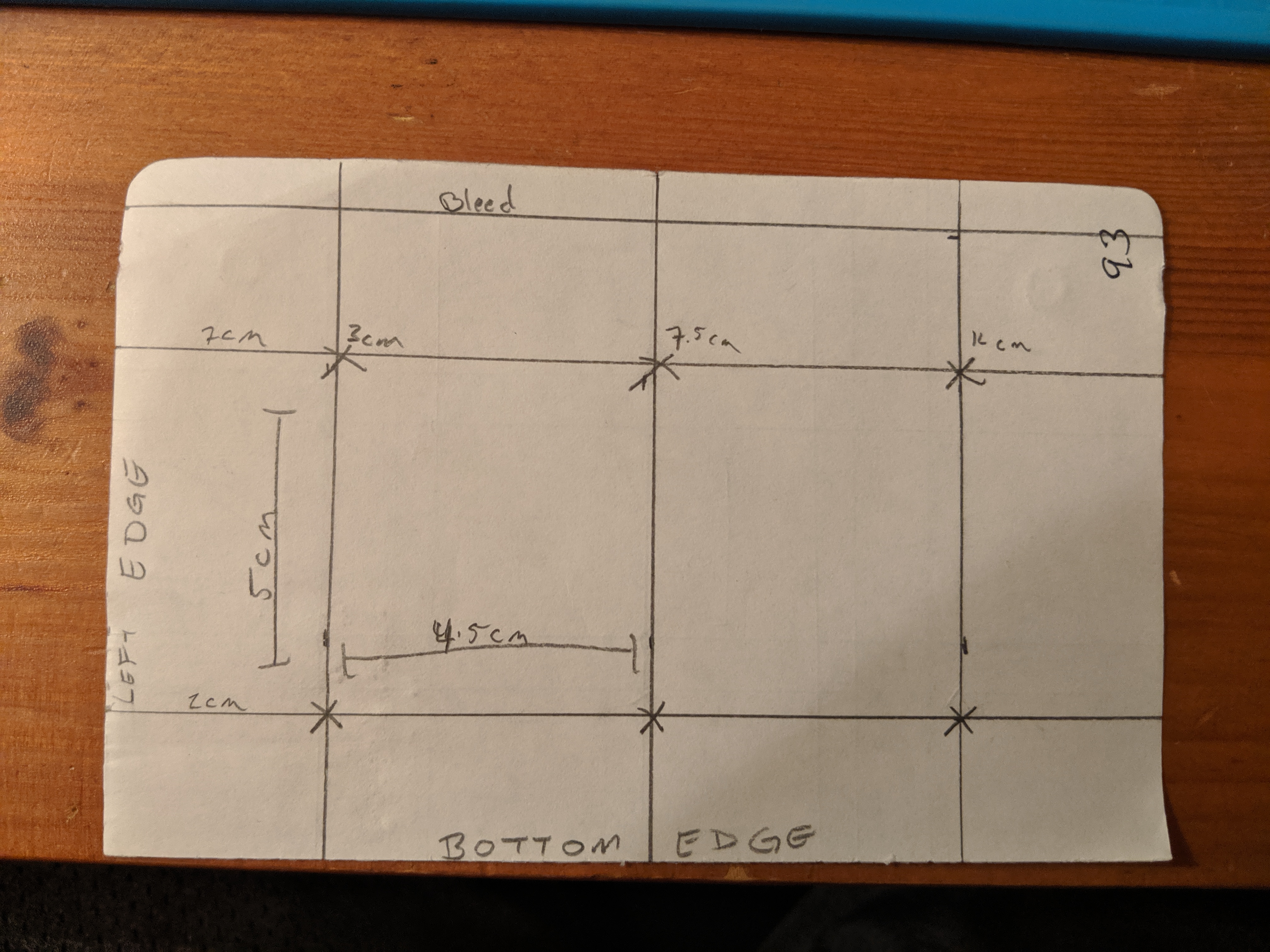
left was to assemble everything. First I made a template on paper to figure out
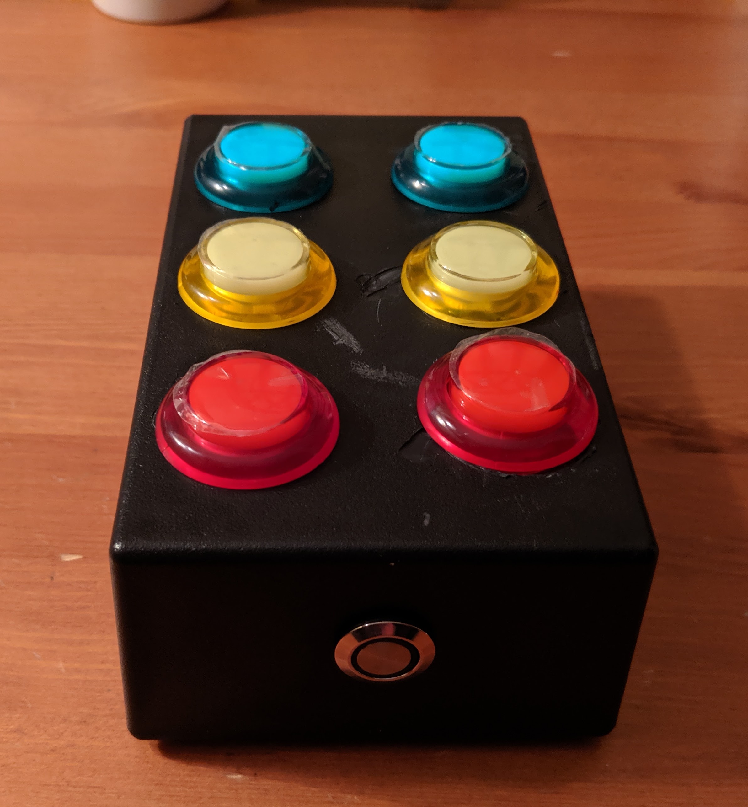
the placement of the buttons. I wanted to make sure that the arcade buttons
were placed far enough apart so that I could fit the power button on the side.
After a lot of measuring and some fiddling I settled on the below layout.
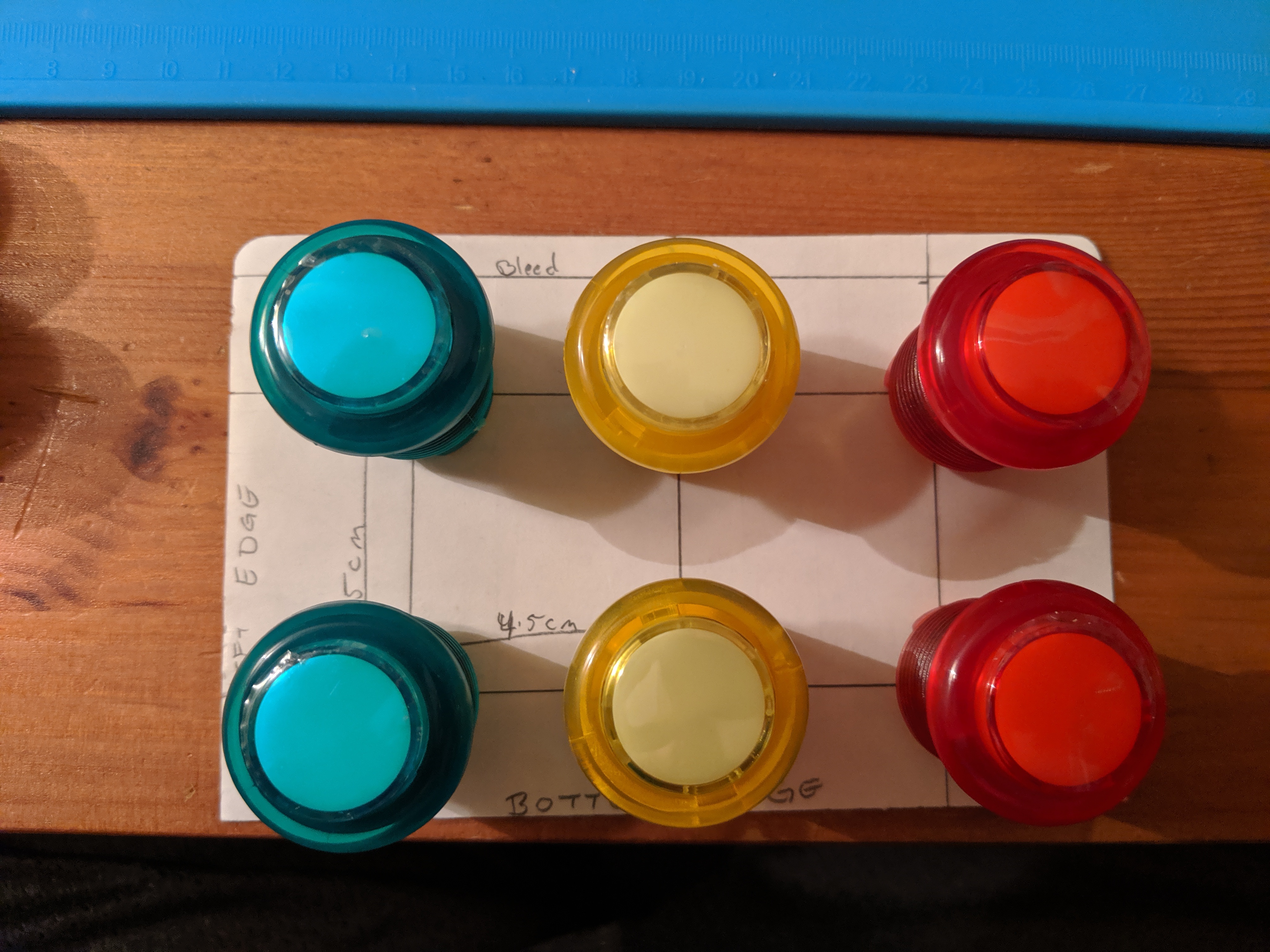
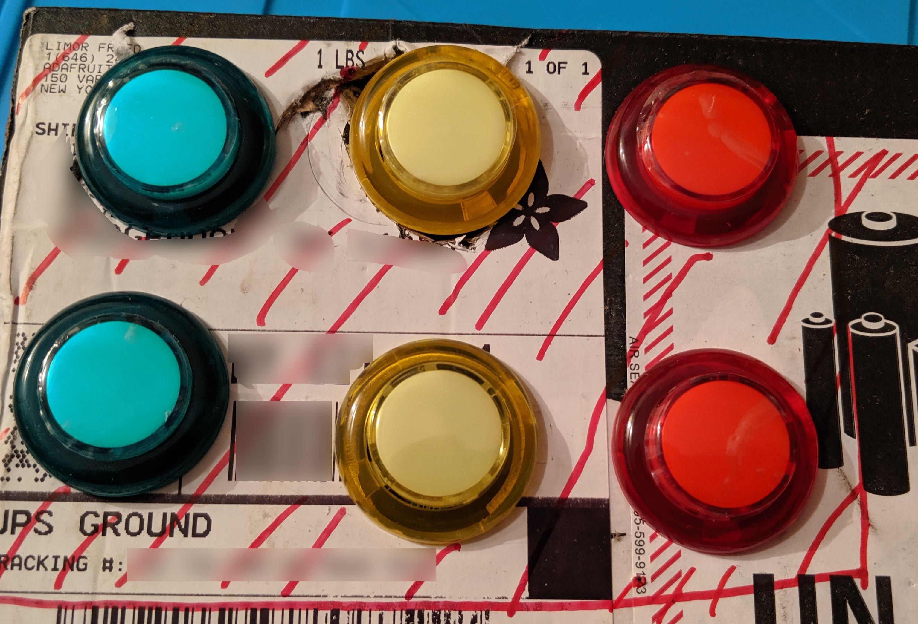
To be sure the spacing worked, I placed the buttons directly on the paper.
This was the third layout I tried. Also, I originally planned on blue, green,
and red buttons. After seeing them lined up, the blue and the green were too
similar in color, so I swapped in the yellow buttons for some contrast.
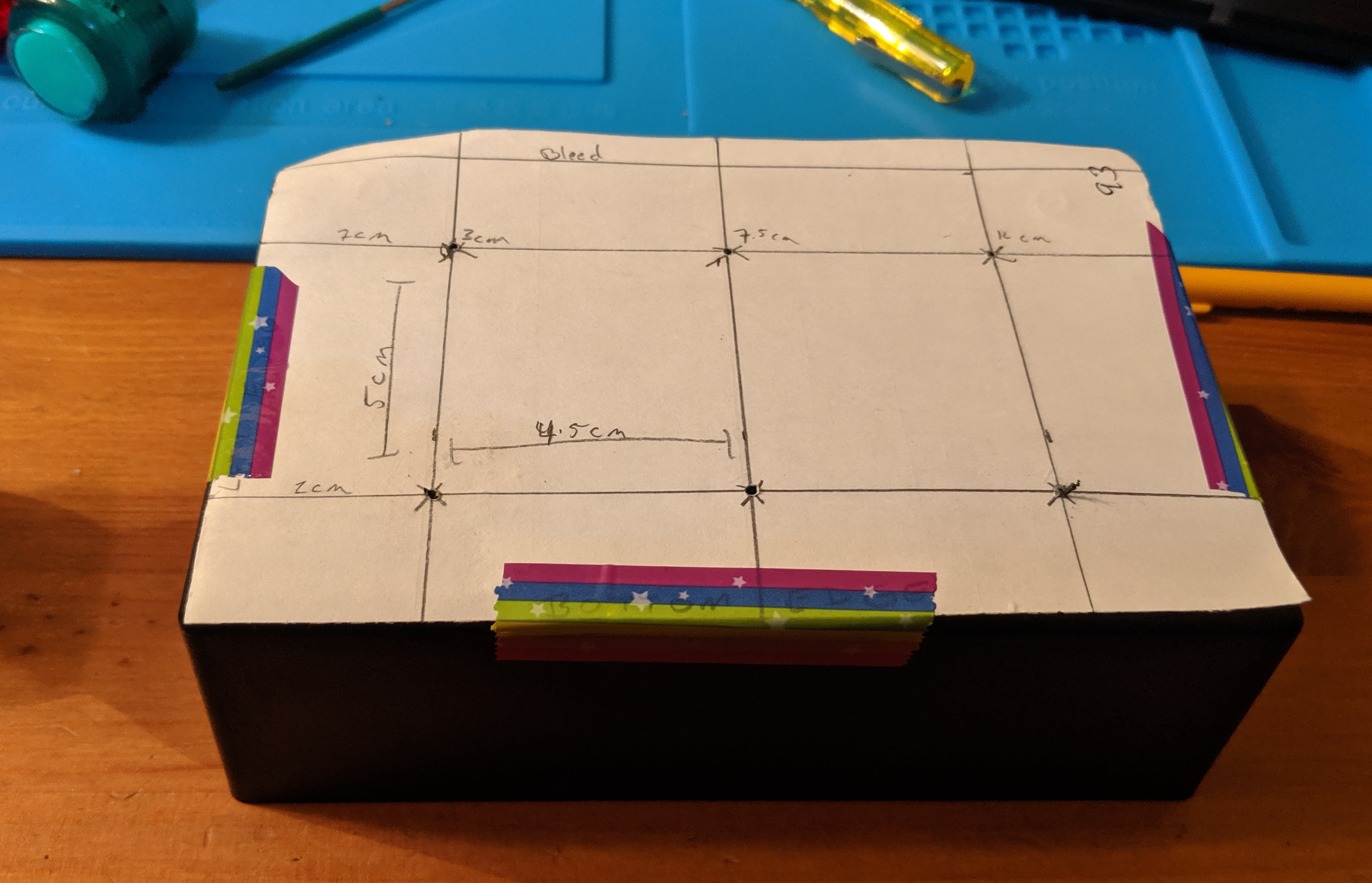
To be absolutely certain, I created a quick mock up a cardboard box. The
layout was just right.
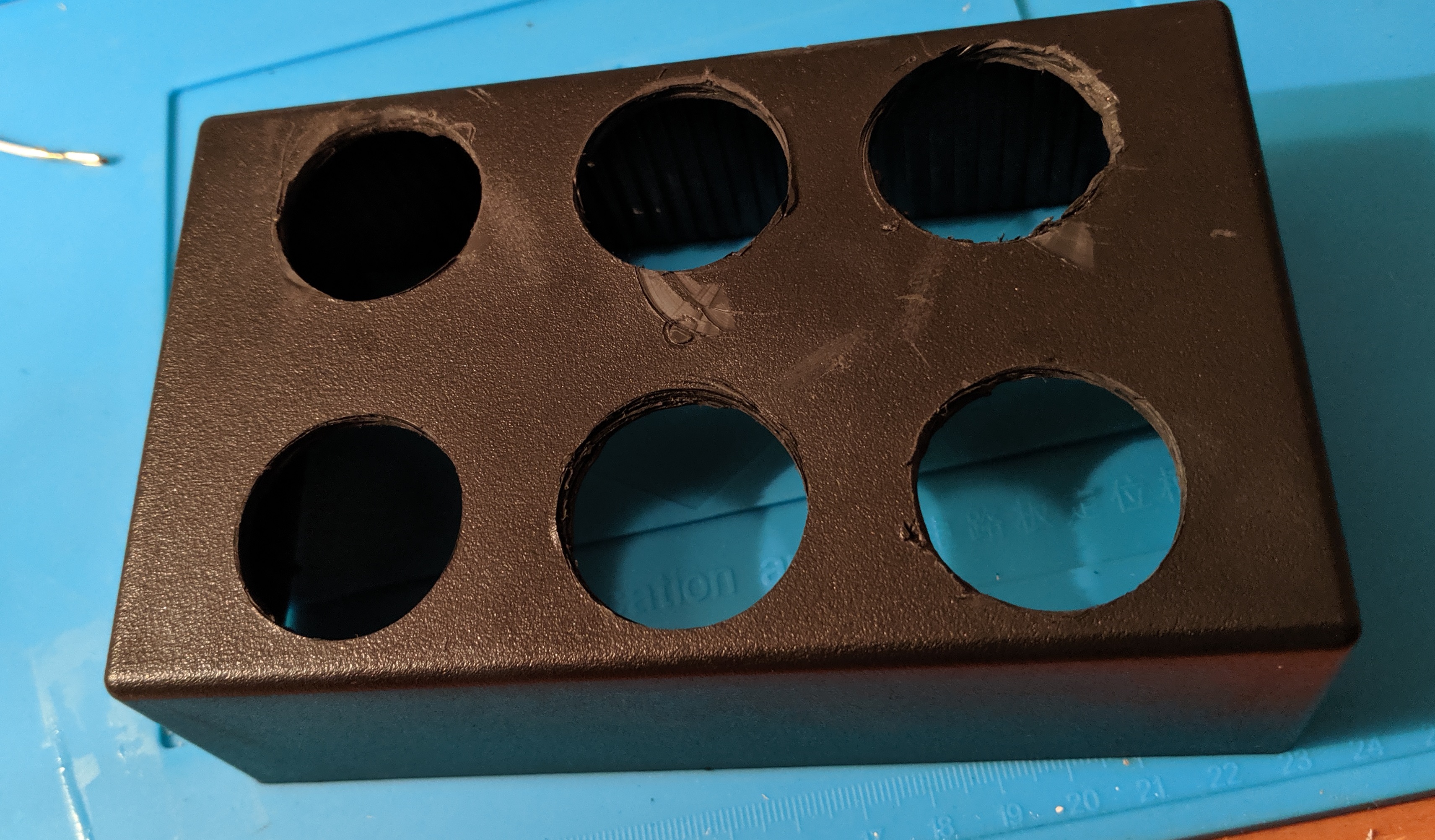
To transfer the layout to the case, I taped the pattern to the top and drilled
1/16th holes in the center.
Forstner bits were used to drill out the 16mm holes for the buttons. It took me
a little bit to get the hang of drilling the holes. Sometimes the drill caught
on the plastic and scratched the surface of the case.
The wires took up more space than I expected. It would have been helpful to
daisy chain all of the grounds across a common wire, removing half of the wires
needed. Also, the rest of the wires could have been cut much shorter or routed
around the edge of the enclosuer, taking up less room.
The fit was tight enough that I didn’t need to mount the feather to the case. The wires held it in place with little to no movement when the bottom was screwed on.
You can see the power button on the side.
Code
With everything assembled it was time to test it out. And it didn’t work.
After a little trial and error, I realized that the keyboard would only work if
my laptop was plugged into it via USB and I had the Arduino serial monitor
plugged in. Looking over my code a bit, I see that I still had a line of code
at the very beginning telling the board not to start up unless it detected a
serial console. Removing that fixed the first problem.
Next, whenever I pressed the volume down or up buttons for a brief moment, the
volume would go all the way to 0 or 100. No in between. It registered as way
too many key presses. Adding a small delay at the end of the loop solved this
problem.
Today’s progress is a bit misplaced in the “Pi Project” folder. I wound up
using my Adafruit Feather 32u4 Bluefruit
LE to emulate a keyboard. Since this is
exactly what it was designed to do, it really wasn’t that hard. Which means it
took me a long time. My goal was to use a Bluefruit LE UART
Friend connected to my Raspberry Pi.
That was beyond my current skills so I decided to take smaller steps. The
Feather has lots of samples doing exactly what I want to do, so I went that
route.
The plan is still to go back to the Pi though since my end goal is to make a
keyboard that gets updates from the computer it’s connected to and I assume
it’d be easiest to do that with a restful API. But that’s for Future Josh to
work through.
Working with
severaltutorials
and code
samples
I was able to create a simple app that sends custom strings of keyboard codes
to whatever device is paired.
Code
Below are the highlights of the application. First it declares the commands to
send as constants, and then polls for button state and sends corresponding
messages.
BLE Commands
Two types of BLE commands are supported, keyboard codes, and control commands.
Keyboard codes are sequences of key downs (key ups are inferred by sending
either the next code, or by sending a message with no codes). Keyboard codes
are sent in a message that is up to 8 bytes long.
The first byte is a bit mask of any modifiers (shift, alt, etc)
The second byte is always 00
Bytes 3 through 8 are the keys to send
For example 08-00-07 is the command for pressing the Windows Key + D. 08
is the left Windows key, and 07 is the letter D (it’s case insensitive, if
you want to have an upper case D, then also send shift).
As stated above, up to 6 keys can be sent at once. So to send abc, that
would be 00-00-04-05-06. But then this would continue to send c repeatedly
since we never sent the key up signal. To do that, just send an empty message
with 00-00.
The other type of message that I’m sending is a control command. This is used
to emulate media buttons like play, stop, and volume control. In my example I
use it just for play (which will also pause). Adafruit’s sample code has a
listing of some available
commands.
Code Logic
Each loop of the main method polls the state of the buttons to determine which
messages to send. It also records its state so the next iteration can either
send the key up signal in the case of the keyboard codes, or to simply not
resend the play command a second time (thereby pausing the music if the button
is held down for more than a fraction of a second).
It’s all pretty hard coded now, but the idea is to have it evolve to be more
configurable over time.
charCMD_MISSION_CONTROL[]="01-00-52";// (Left) Control + Arrow UpcharCMD_APP_WINDOWS[]="01-00-51";// (Left) Control + Arrow DowncharCMD_SHOW_DESKTOP[]="08-00-07";// (Left) Window + DcharCMD_VOLUME_UP[]="00-00-80";// Volume UpcharCMD_VOLUME_DOWN[]="00-00-81";// Volume DowncharCMD_VOLUME_MUTE[]="00-00-7F";// Volume MutecharCMD_F14[]="00-00-69";// F14charCMD_KEYS_UP[]="00-00";// No keys heldvoidloop(void){intpressed=0;intplayPressed=false;if(digitalRead(5)==LOW){pressed++;printKeyboardCode(CMD_MISSION_CONTROL);}if(digitalRead(6)==LOW){pressed++;printKeyboardCode(CMD_APP_WINDOWS);}if(digitalRead(9)==LOW){pressed++;printKeyboardCode(CMD_SHOW_DESKTOP);}if(digitalRead(10)==LOW){playPressed=true;if(!playButtonPressedLastTime){printControlKey("PLAY");}}if(digitalRead(11)==LOW){pressed++;printKeyboardCode(CMD_VOLUME_UP);}if(digitalRead(12)==LOW){pressed++;printKeyboardCode(CMD_VOLUME_DOWN);}if(pressed<1&&buttonsPressedLastTime>0){// send the key-up commandprintKeyboardCode(CMD_KEYS_UP);}buttonsPressedLastTime=pressed;playButtonPressedLastTime=playPressed;}voidprintKeyboardCode(charkeys[]){ble.print("AT+BleKeyboardCode=");ble.println(keys);}voidprintControlKey(charkeys[]){ble.print("AT+BleHidControlKey=");ble.println(keys);}
Wiring
Wiring is pretty simple for this device since it’s essentially made for this
use case. I strung together 5 buttons with a common ground, and plugged each of
the buttons into the pins 5, 6, 9, 10, 11, and 12. I have a Battery on order,
and will wire up that and a power switch once they arrive.
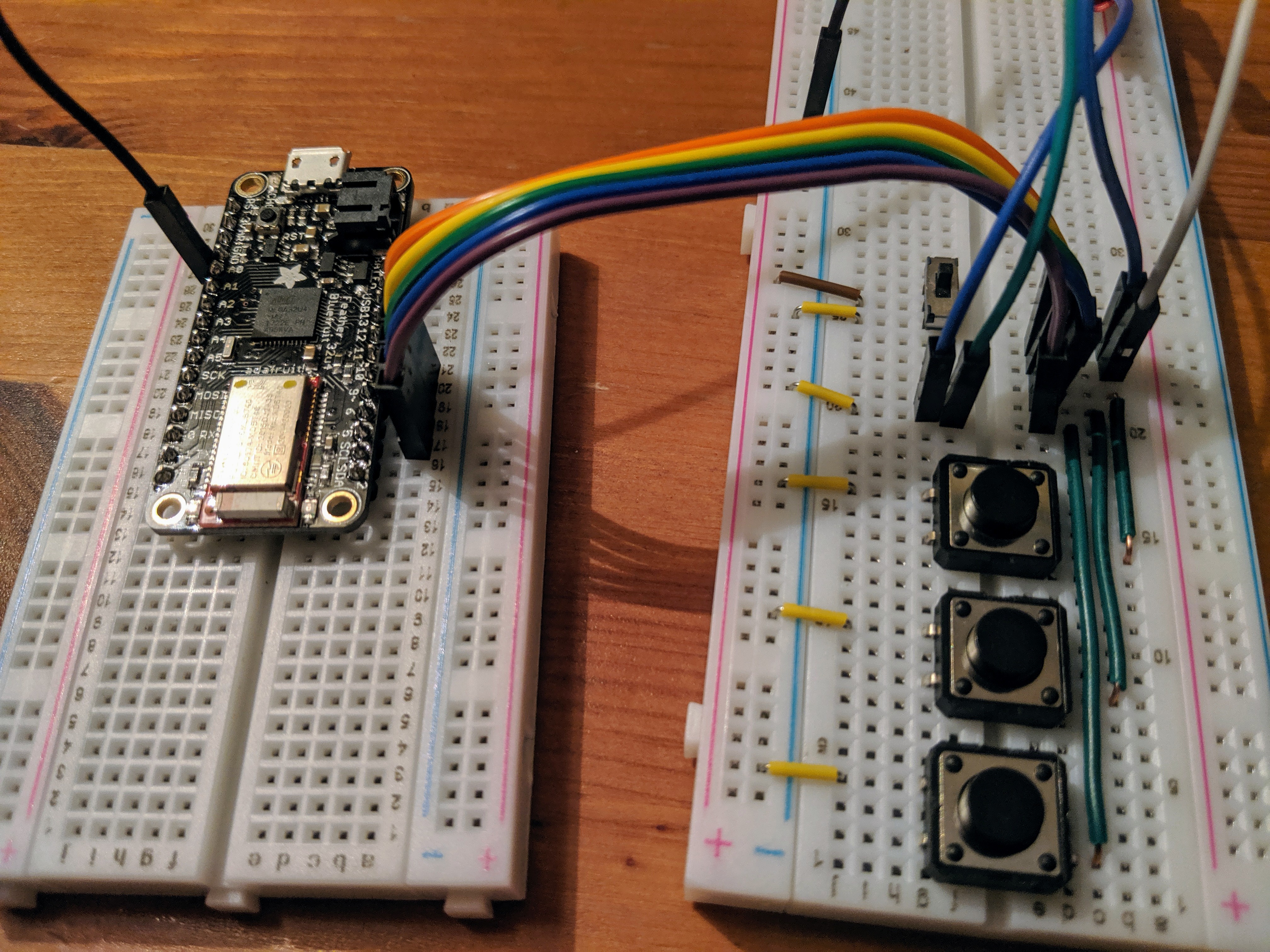
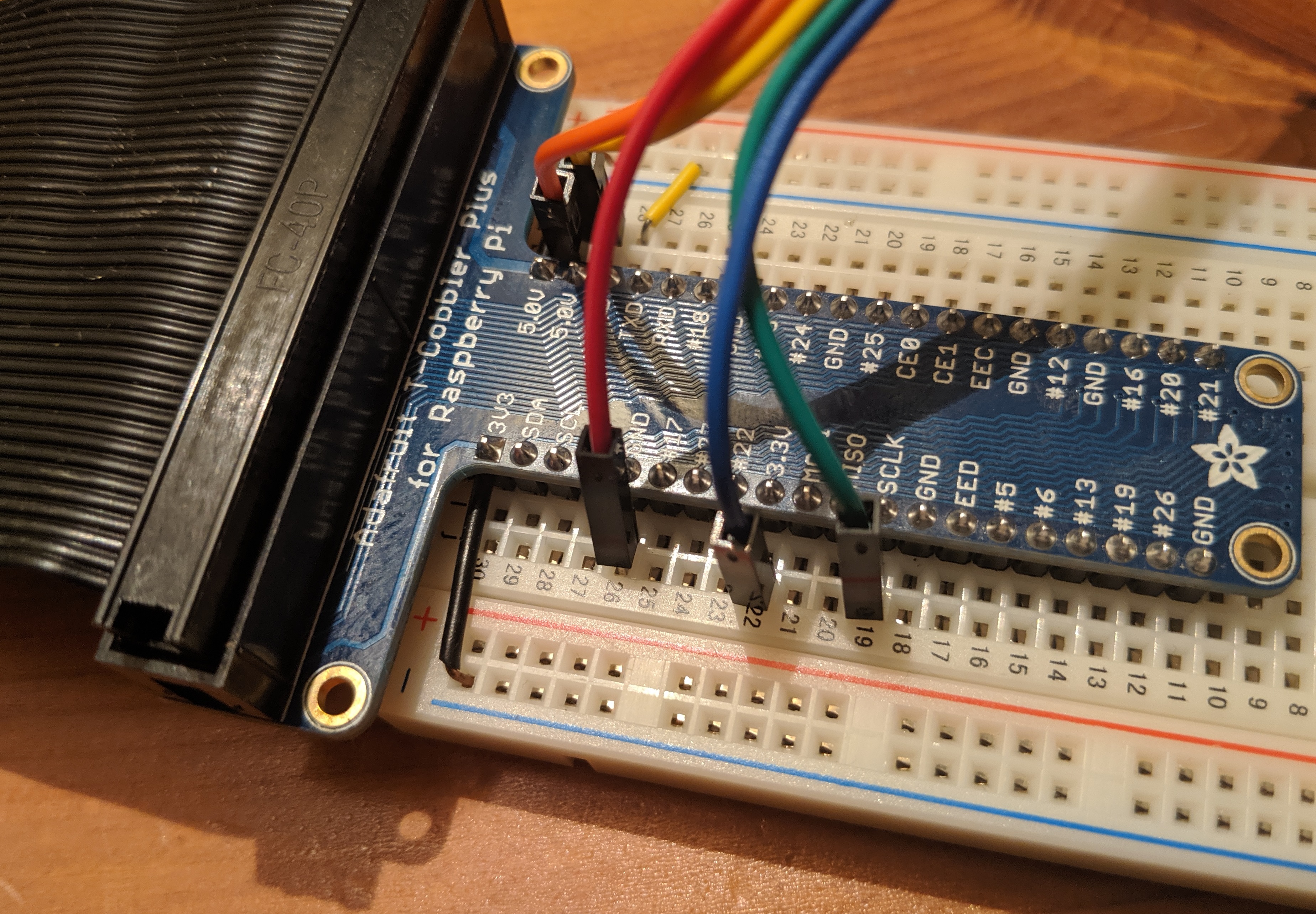
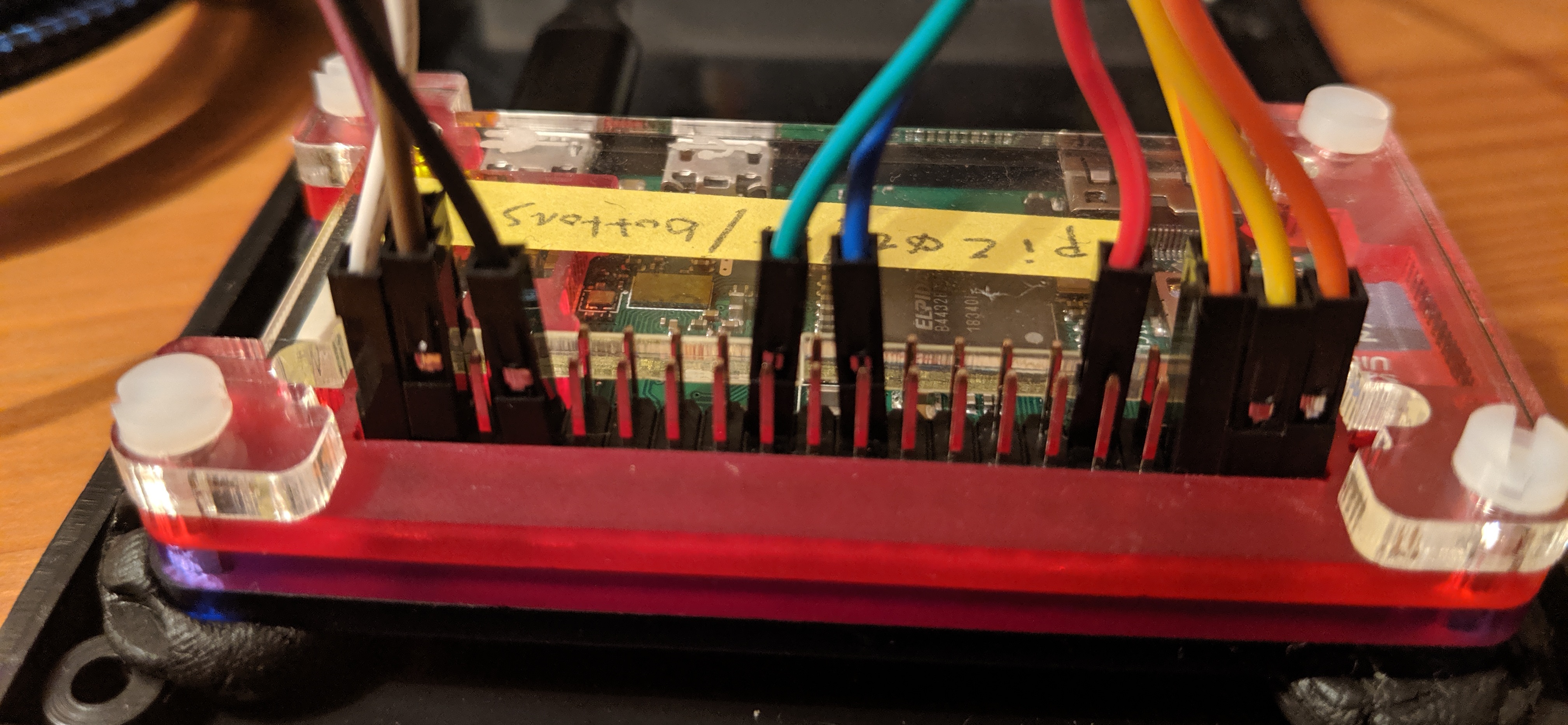
I followed a mix of instructions, including
Adafruit,
and
ElectronicWings
to start playing with talking to and from my Raspberry Pi over a serial
connection from my Windows Surface. I used a TTL
cable
from Adafruit.
Following are instructions for setting up communication between a Raspberry Pi
3 (not a zero) and a Windows laptop.
Setting up the Pi
First thing to do on the Pi is to turn of shell login via serial port.
sudo raspi-config
Select “Interfacing Options”
Select “Serial”
When asked “Would you like a login shell to be accessible over serial?” select no
When asked “Would you like the serial port hardware to be enabled?” select yes
Reboot the device
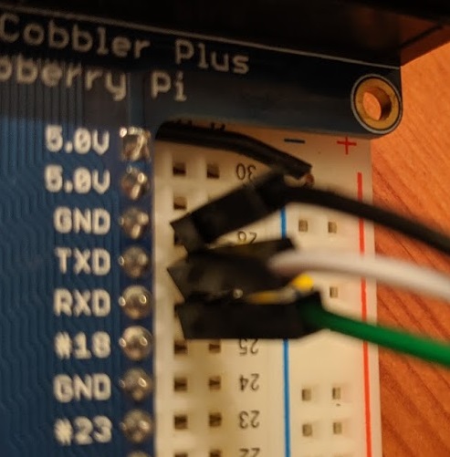
Next is to connect the cable to my Pi. My Pi was powered by USB already, so I
didn’t connect the red (5v) wire to the Pi. Just hook up the wires up as
follows, (or see the picture below).
Black -> Ground
White -> TXD
Green -> RXD
Setting up the Windows Laptop
First step is to install the drivers on my laptop for the cable. I had the
older version of the cable, so I needed the Prolific
Drivers.
There’s also a link to this from the Adafruit tutorial.
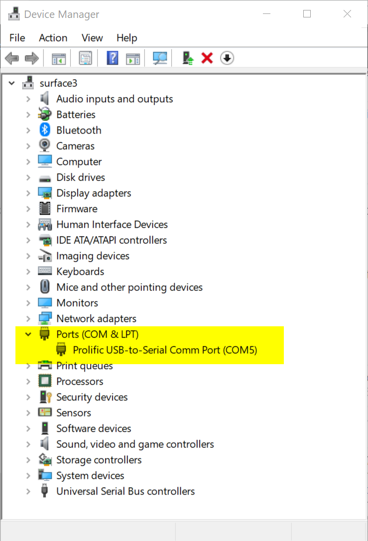
Now once the the USB cable is plugged into the laptop it will show up as a new
COM port. To figure out which one it is either find it in the Device Manager
or use the mode command.
>mode

Status for device COM5:
-----------------------
    Baud:            9600
    Parity:          None
    Data Bits:       8
    Stop Bits:       1
    Timeout:         OFF
    XON/XOFF:        ON
    CTS handshaking: OFF
    DSR handshaking: OFF
    DSR sensitivity: OFF
    DTR circuit:     ON
    RTS circuit:     ON


Status for device CON:
----------------------
    Lines:          32766
    Columns:        112
    Keyboard rate:  31
    Keyboard delay: 1
    Code page:      437
Notice that the mode command will also conveniently print out the baud rate
(you’ll need this in the next step). This information is also available from
device manager too by going in to the port’s properties.
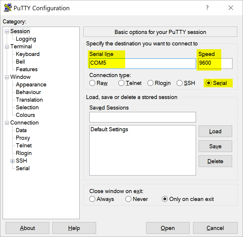
Open up the serial port in PuTTY, using the COM5 port found above.
Connecting
Back on the Pi find the correct serial port. As I understand it (which is 90%
likely to be wrong), on the Raspberry Pi 3, the UART port is going to be
ttyS0 and the Bluetooth port (also serial) will be ttyAMA0. ls -l /dev
will give you information about the ports.
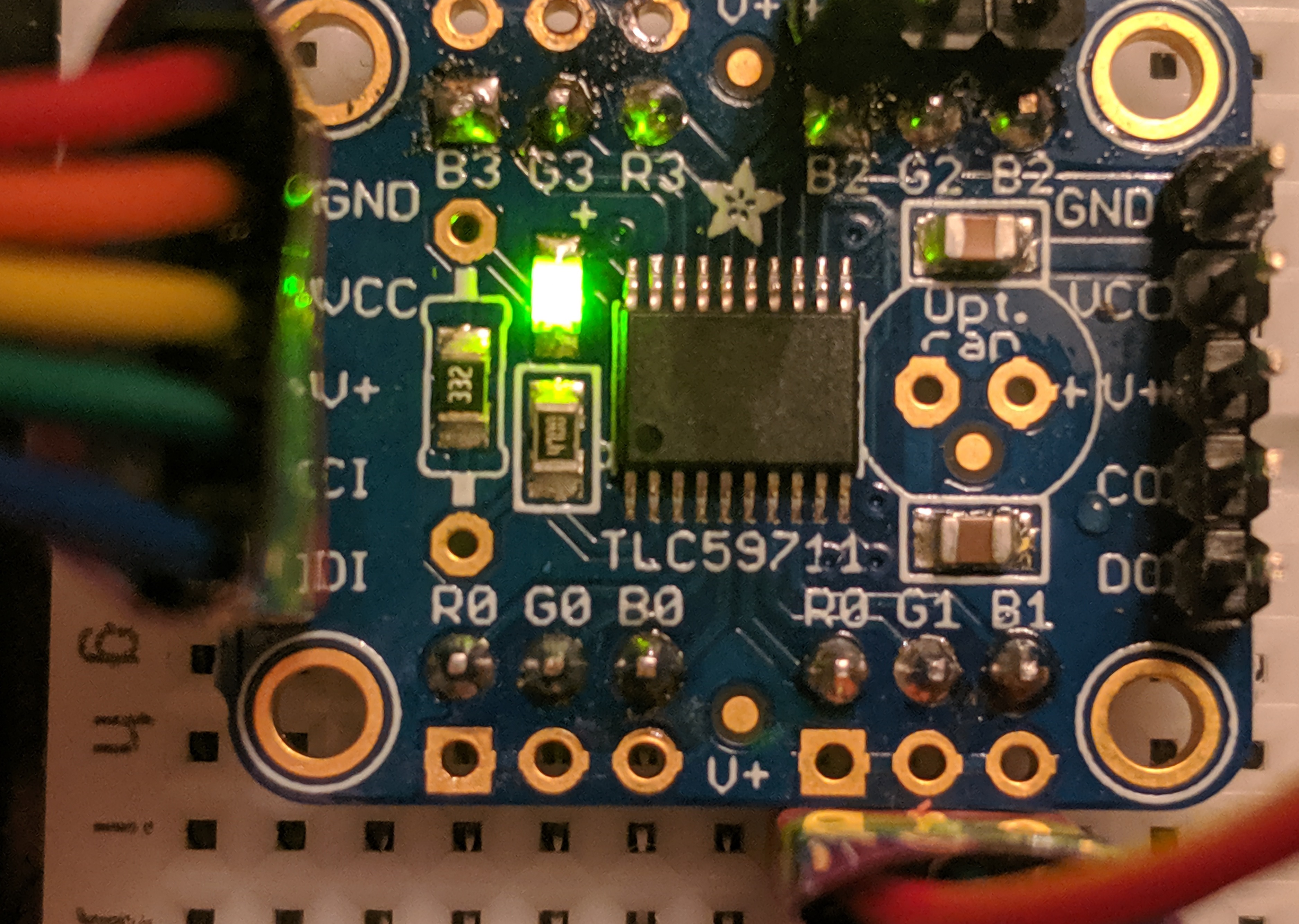
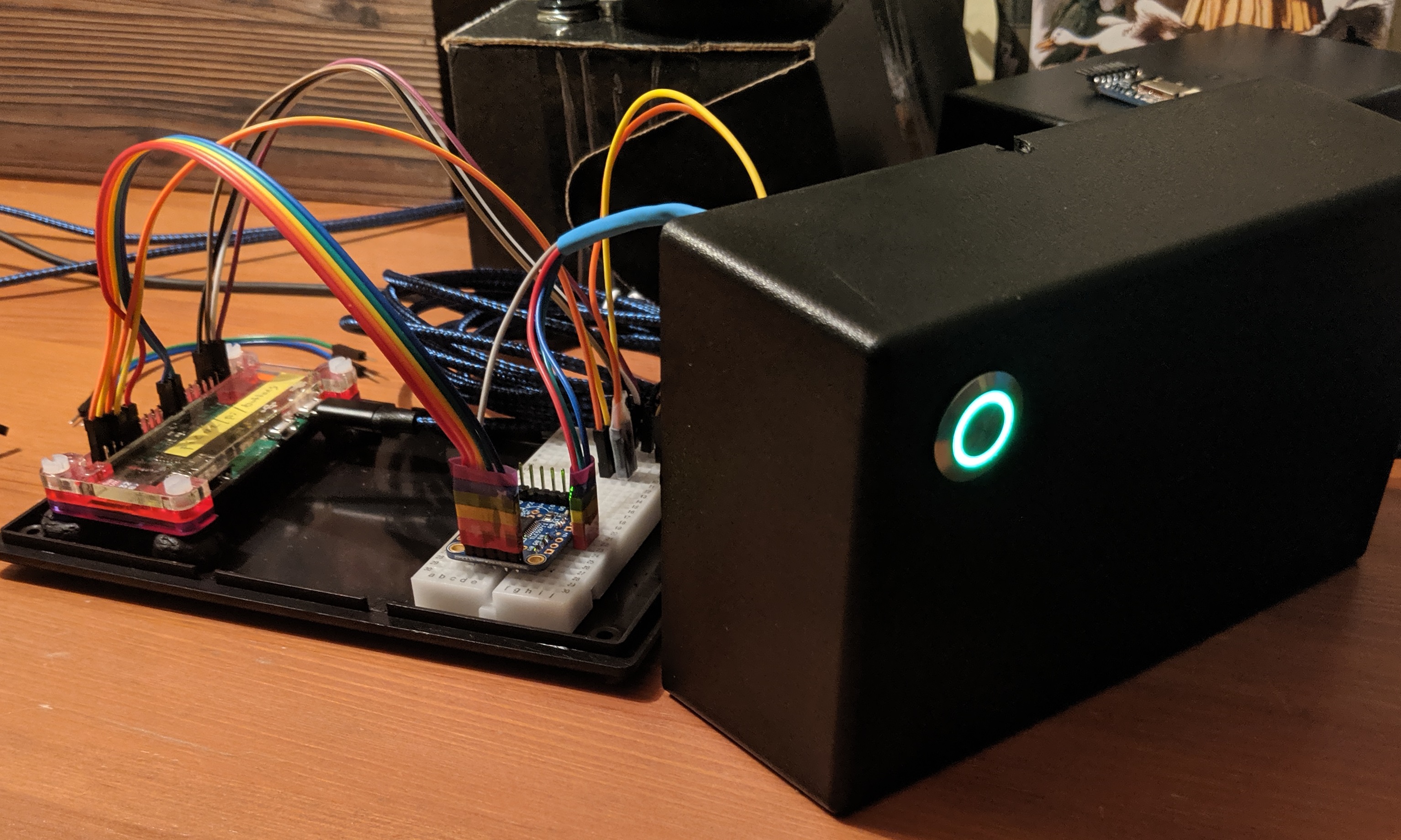
This weekend I focused on getting the GB LED in my power
button to work. I needed to use an SPI
PWM board from Adafruit to control the
LED. You can see it working above. When the device is on, the light is green.
Hold the button down for 5 seconds and it turns purple, signaling that when you
release it the device will power down. When it powers down the light turns
(and stays) red.
I have detailed instructions on using the PWM with a Raspberry
Pi.
A couple of highlights (mistakes) that didn’t make it into the post are worth
noting here.
First off, I didn’t do a great job soldering the header pins to the board. I
had too much solder on some of the pins, which resulted in a sphere on the end
of the board that didn’t make enough contact to keep the pin firmly attached.
Which is to say the pins fell out. Next, I realized that I had soldered the
header on to the output side of the board, not the input, meaning that it was
ready for me to daisy chain on another board… but that I couldn’t use the
current board without soldering the other side on. A textbook case of Murphy’s
Law.
All of these soldering mistakes meant it was time to break out the soldering
iron and fix my mistakes. I resoldered the bad pins, and added another header
to the CORRECT side of the board. While I was there I added a male header to
expose the voltage pinouts. One convenient mistake I had made weeks ago was
soldering a female jumper wire to the voltage pin on my power LED. With the
new male header on the board, it was easy to wire this up.
Speaking of wiring, I used some rainbow tape to on the red, green, and blue
jumpers coming from the power LED to keep them organized, and then plugged them
into my breadboard, connecting them to the PWM board. From there, wiring up
the Pi to the board was pretty simple. I used some more rainbow tape to keep
those wires in order and make it easy for me to connect and disconnect the
board entirely.
Next it was time to dip into Python to integrate the LED to my existing volume
controller app. The code can be found in my Day 7 pull
request. The majority of went
into a dedicated
RgbLed
class. It doesn’t expose a lot of the features, but enough for now.
Pictures
Here it is fully wired and turned on with the lid off
A Pulse Width
Modulation driver allows
you to either connect a whole bunch of regular LEDs with just a few pins (and
the PSI protocol).
The 12 channel driver can support 12 LEDs. Additional drivers can be daisy
chained on allowing near limitless LEDs. If regular LEDs don’t interest you,
you can use 3 channels to drive a single RGB LED (for 4 total per module).
Optionally save your imports with pip3 freeze > requirements.txt
Hardware Setup
Optionally follow the instructions on Adafruit’s site to solder on headers so the module can be plugged into a breadboard.
Optionally solder on headers to the voltage pins on the board. This helps wiring when it’s inconvenient to just wire the LED’s leg directly to power.
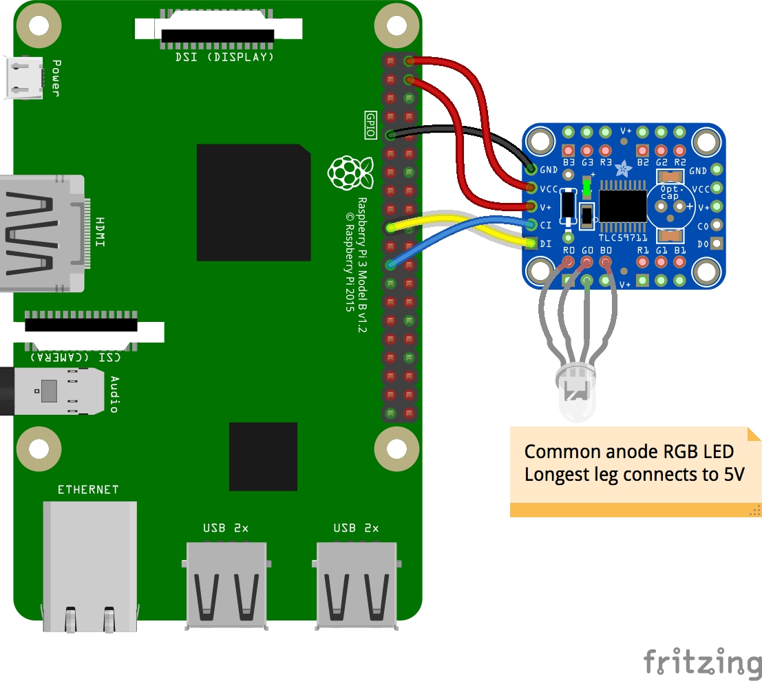
Wire it up! Use the below table or image. Make sure that you orient the board correctly and that you’re plugging into the input side and not the output side
The table goes from the top down on the pins on the left side of the module. When there are multiple pins to choose from, I have bolded the pin that I used.
PWM (TLC59711)
Raspberry Pi
Pi Pin Number
GND
Ground
6, 9, 14, 20, 25, 30, 34, or 39
VCC
5v Power
2 or 4
V+
5v Power
2 or 4
CI
Serial Clock (SLK)
17
DI
MOSI
19
After this, plug an RGB LED in to any of the RGB pins on the board with the longest pin going to one of the 12 voltage pins.
Testing it
Fire up a python3 REPL and import everything from above and then start turning on some LEDS:
importboardimportbusioimportdigitalioimportadafruit_tlc59711spi=busio.SPI(clock=board.SCK,MOSI=board.MOSI)rgb=adafruit_tlc59711.TLC59711(spi)# Full Red, Green, or Blue (mix/match as much as you like)
rgb[1]=(65535,0,0)rgb[1]=(0,65535,0)rgb[1]=(0,0,65535)rgb.b1=32768rgb.g1=16384rgb.r1=8192rgb.red_brightness=10rgb.green_brightness=10rgb.blue_brightness=10
Today was a simple day. I wired up the on/off button. Pressing it when it’s powered off powers it on. Holding it while it’s on starts a clean shutdown. My next step is to use the LED in the button to provide status (shutting down, on, release to turn off, etc).
I’ve wanted to have a proper IDE environment on my Windows machine that can
execute code on my Raspberry Pi. Turns out that there’s a new VS Code extension
that purports to do just that. Except if you read the fine print it currently
only supports an x86_64 Linux-based OS.
But still, it’s worth keeping an eye on the Remote
SSH
extension. It’s new as of a few days ago and I expect that they’ll make
improvements and allow more environments over time.
In the mean time, I’m trying out SSH
FS,
which allows you to treat an SSH host as a workspace. By default it treats the
host’s entire file structure as your workspace, so make sure you specify a
root. It’d be more ideal if you could run commands directly on the host. But
you can always just ssh to the host in Code’s terminal.
Once the extension is installed, run the command SSH FS: Edit configuration
to add a configuration. Once you’ve configured it (see below), run the command
SSH FS: Connect as Workspace folder and select the configured host.
After working with this for a few hours it proved to be unreliable. When it
was working it was great, but there were plenty of times when trying to set up
the configuration was flaky. This resulted in not always being able to read
the configuration which meant that I couldn’t connect.
In the end it was easier to just remote in to the pi and use vim.
I didn’t have a whole lot of time this weekend, but I did make some great
progress. I wrote a quick
Flask
service that used a
github project I found to
control the volume. After a quick update to the
piboard
to connect to my Windows laptop. A quick restart of the Pi and it actually
worked!
Not only am I late with this status report for last Sunday. I
finished getting everything wired up and cleaned up my desk with 3
minutes to spare before the season premier of Game of Thrones. There
was no chance I was going to write up a status report at that point.
Since then I’ve done more work so it’s not really a true status for
day 4. Let’s call it 4.5.
Software
I decided to shelve any work towards getting the BlueTooth
connectivity to work for the time being. I was putting a lot of
effort into that without a lot of results. My goal for an MVP is now
to get a box that has a volume knob that works. The quickest route
without too much throwaway work is a device that makes rest calls to
a configured laptop running a webservice that handles the volume
control. This will let me concentrate on getting the electronics up
and running and the physical box built.
Towards that, the first thing I did was refactor out the
SimpleButon
and
SimpleRotary
scripts I had from last week into python classes and use them in a
python script that calls a webservice.
With that done, I quickly transferred the proof of concept to a Pi
Zero W. Or at least I tried to. For whatever reason, whenever I
tried to do a git pull the command line hung. After some googling
I tried a last ditch attempt of just updating the OS with
sudo apt-get update
sudo apt-get dist-upgrade
Surprisingly, that actually did the trick. Now my only issue is that
I never installed the prereqs on the Zeros. So a few apt-gets later,
and I’m back in business.
Once the code’s running on the Pi, I have to figure out how to get
it to run whenever it stats. Some more googling and I find Pi’s
documentation on
rc.local.
sudo vim /etc/rc.local
Hardware
Coding. Done. Linux administration. Done. Next up is actually making
the box.
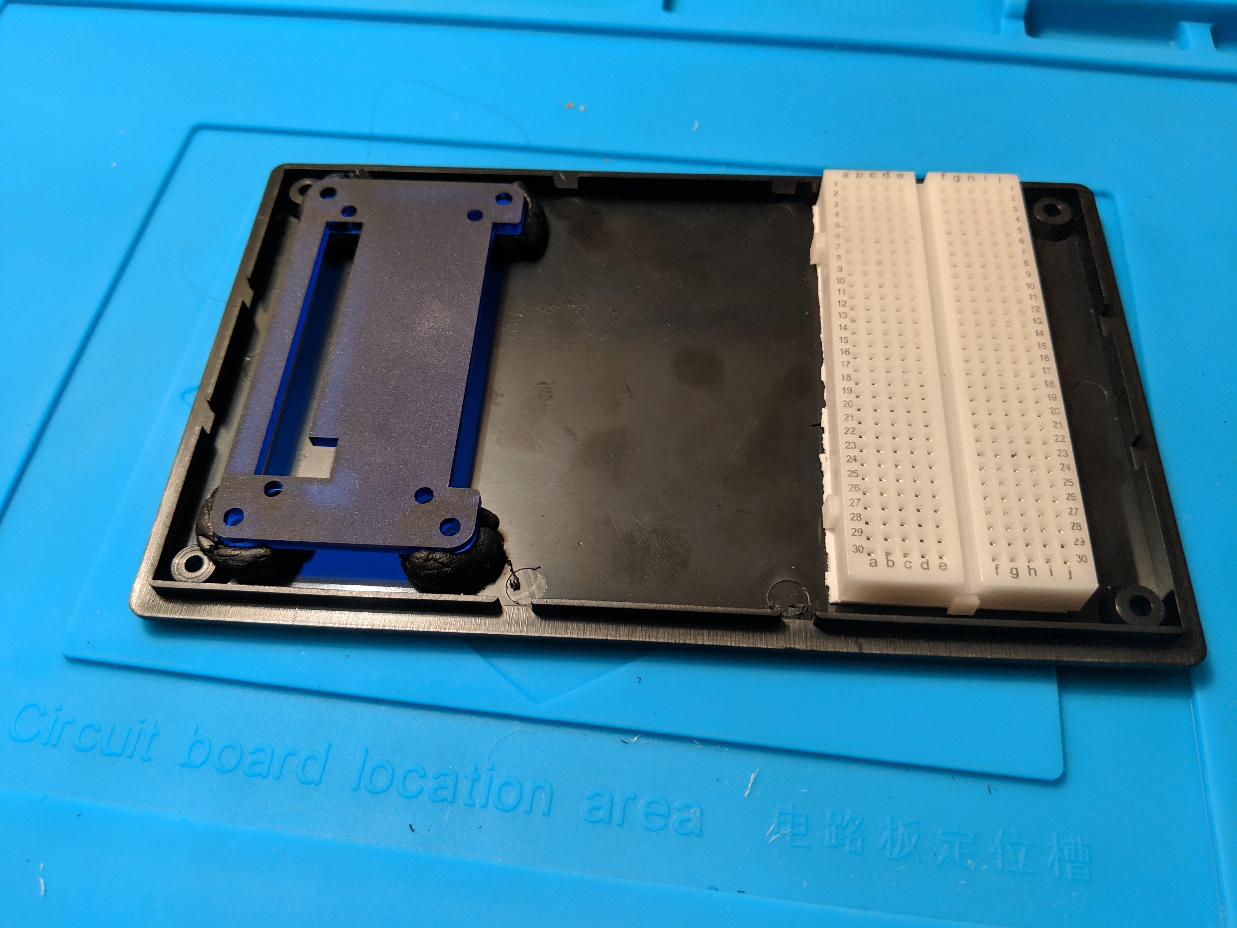
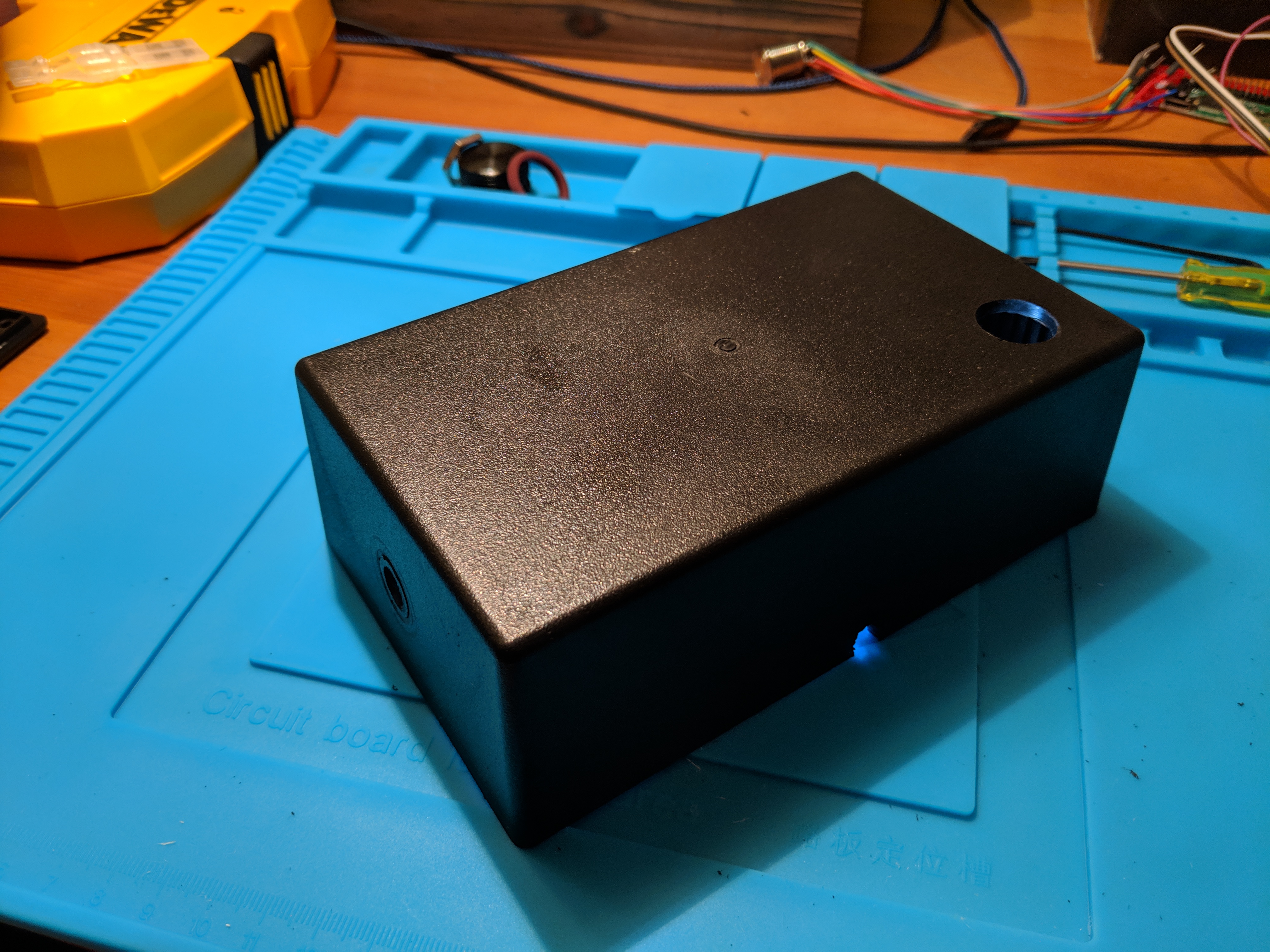
A few weeks ago I picked up a black plastic enclosure from
Tinkersphere.
To make it easy to expand in the future, I used the glue backing on
the back of an extra mini breadboard to affix it to the bottom of
the case. I had to take the power rails off first so it would fit in
the slot.
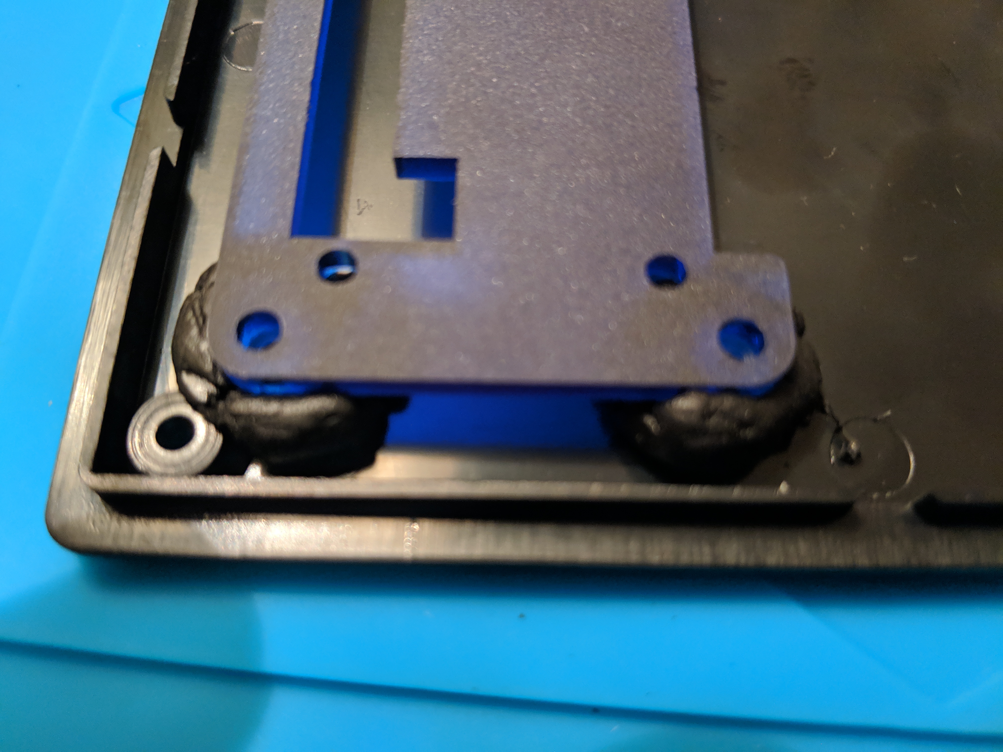
Next, I use Sugru on the bolts of my PiBow
case to affix it to case. I used the full assembled case to ensure
that there was sufficient space for the bolts, but removed
disassembled the case and left only the bottom plate and the bolts
while it set. I’m actually pretty surprised it worked so well.
The Sugru is solid enough that it didn’t ooze anywhere it wasn’t
supposed to. I kind of want to try the same thing with a glue gun
since it’s a little cheaper and easier to have on hand (my Sugru was
technically expired…). I just don’t think it’ll work as well.
Now on to the top. I used a 15mm Forstner bit to drill a hole in the
top for the power button. Then I used a 16mm bit to widen it because
I misread the size on the button.
I used standard drill bits to make a 5/16” hole in the side for the
rotary encoder. This time I started with a quarter inch bit on
Sunday, and then had to buy the 5/16” bit during the week. It was a
perfect fit with the additional 1/16” inch.
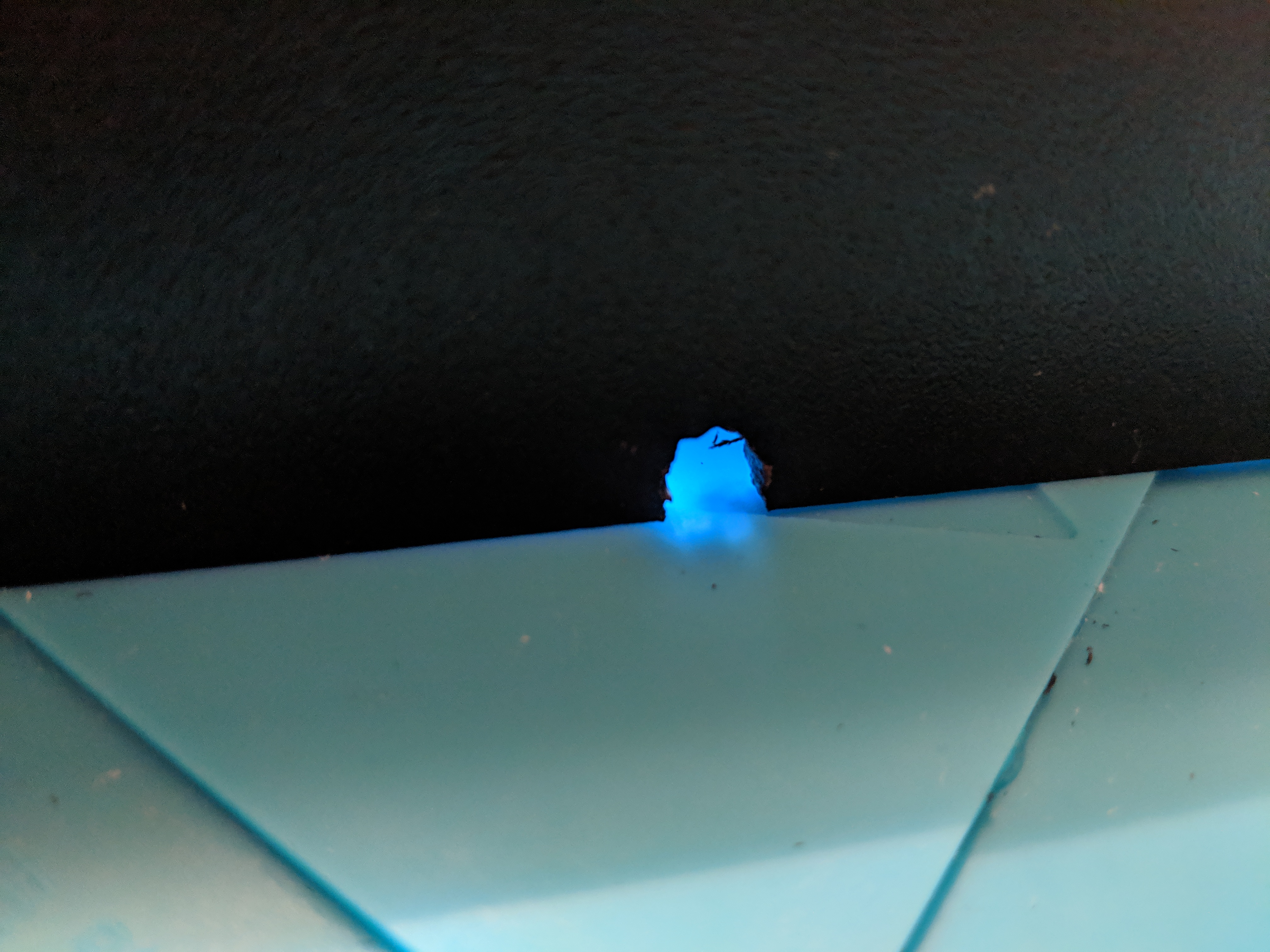
I couldn’t figure out how to cleanly get a small hole for the power
USB cable in the bottom of the case. I went drilling a hole near the
edge and then using my Leatherman to whittle the notch to the
desired size. Worked well enough, but it wasn’t as smooth as the
other holes.
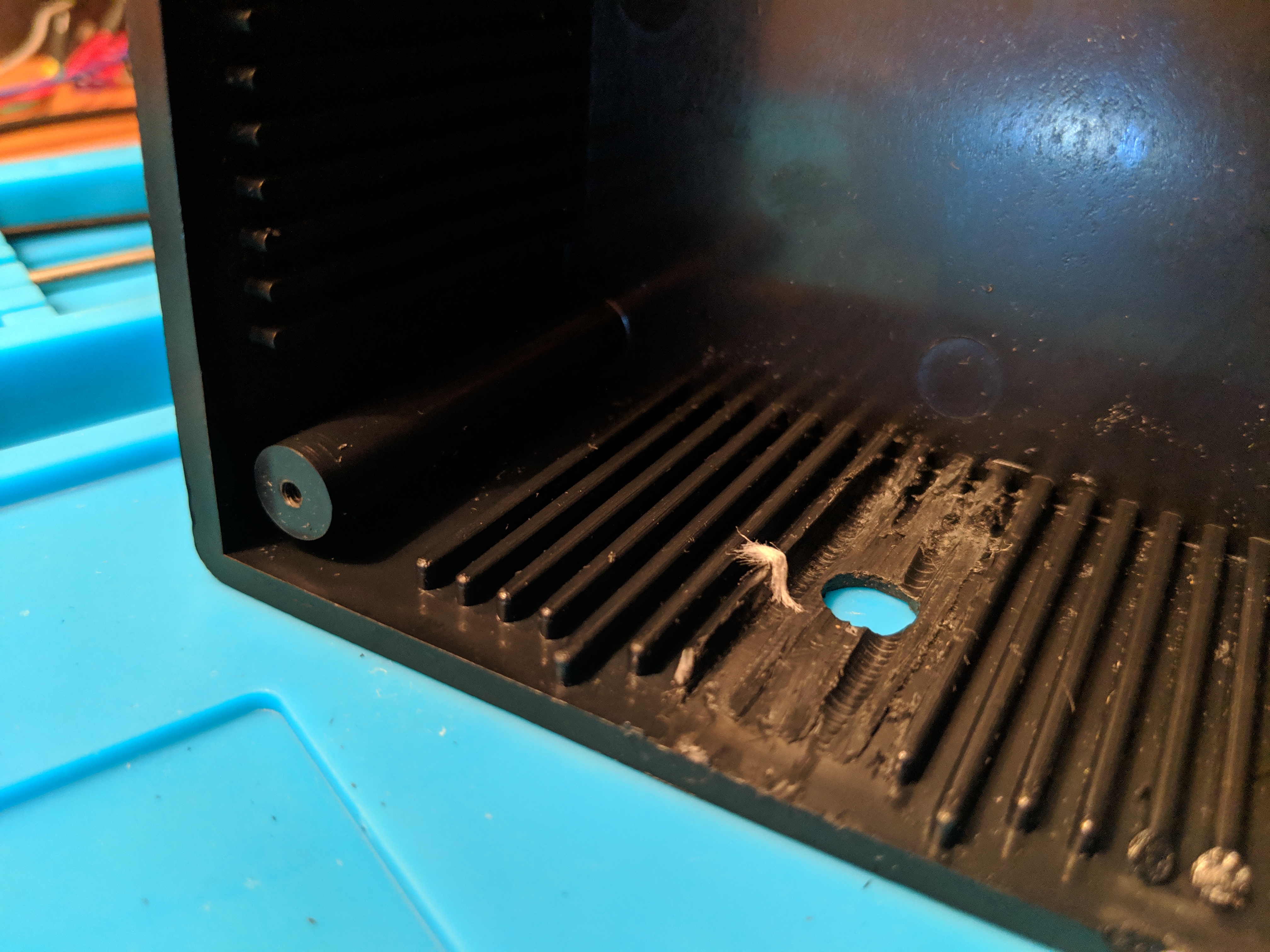
I needed to get rid of the ridges on the interior side for the
encoder to sit flush and extend far enough out. I didn’t have any
better ideas so I grabbed a drill bit a little larger than the space
between the grooves. I used that to drill out some of the ridges
and then went in with the blade of my Leatherman to remove the rest.
Next the file on the Leatherman helped smooth out any uneven ridges.
Not super pretty, but it worked; the encoder sat flush.
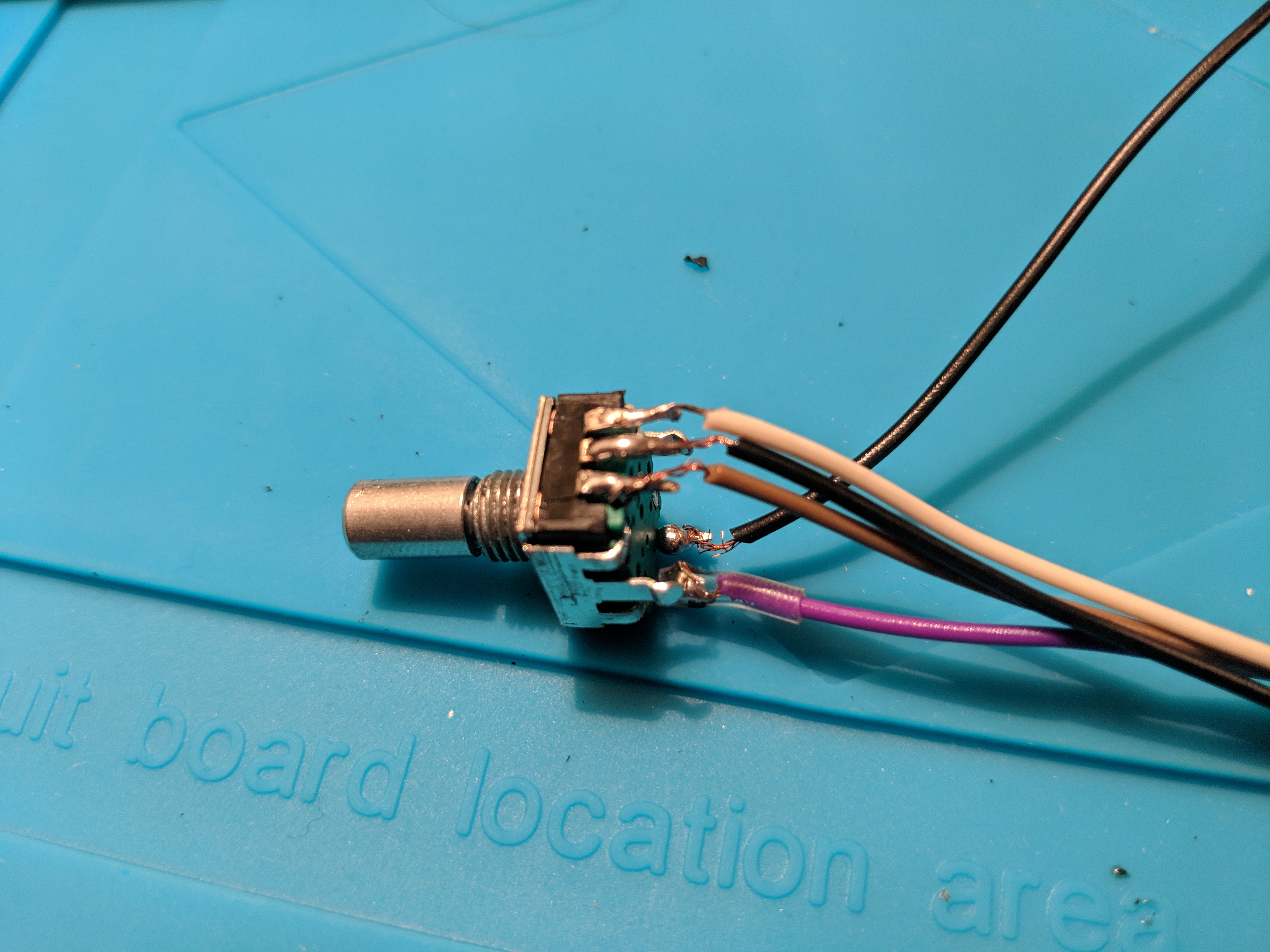
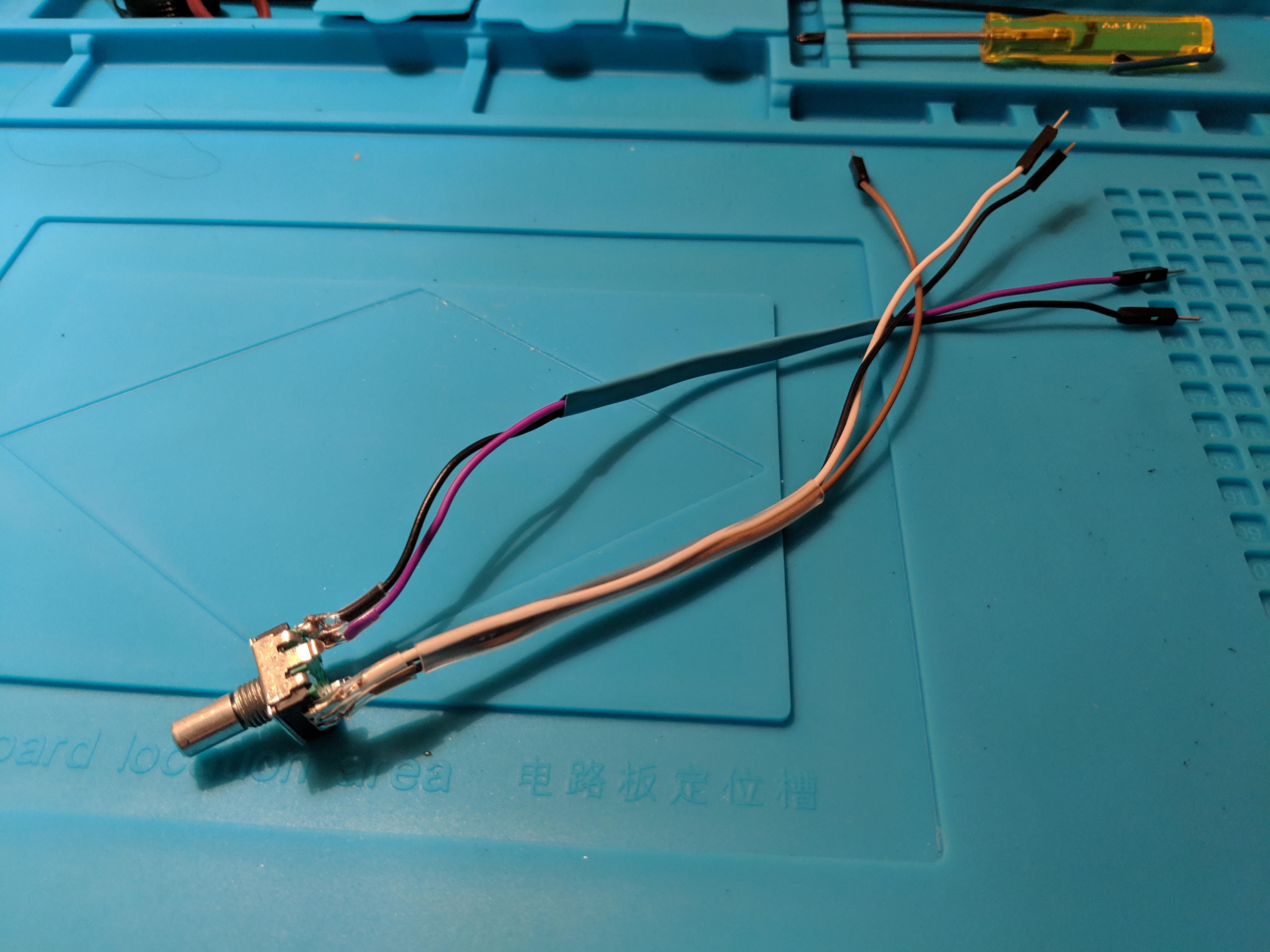
Speaking of the encoder, I was concerned about how I was going to
attach the wires to it in reliable way. I didn’t have any better
ideas, so I figured now was a good enough time as any to learn how
to solder.
Including burning myself (twice), it went much better than I
expected. I cut off one end of some jumper wires and soldered them
on to the encoder and then button. I was on such a roll I even
soldered the head on to a TLC5947 from Adafruit. I plan on using
that in my next step to power the RGB light ring on the button.
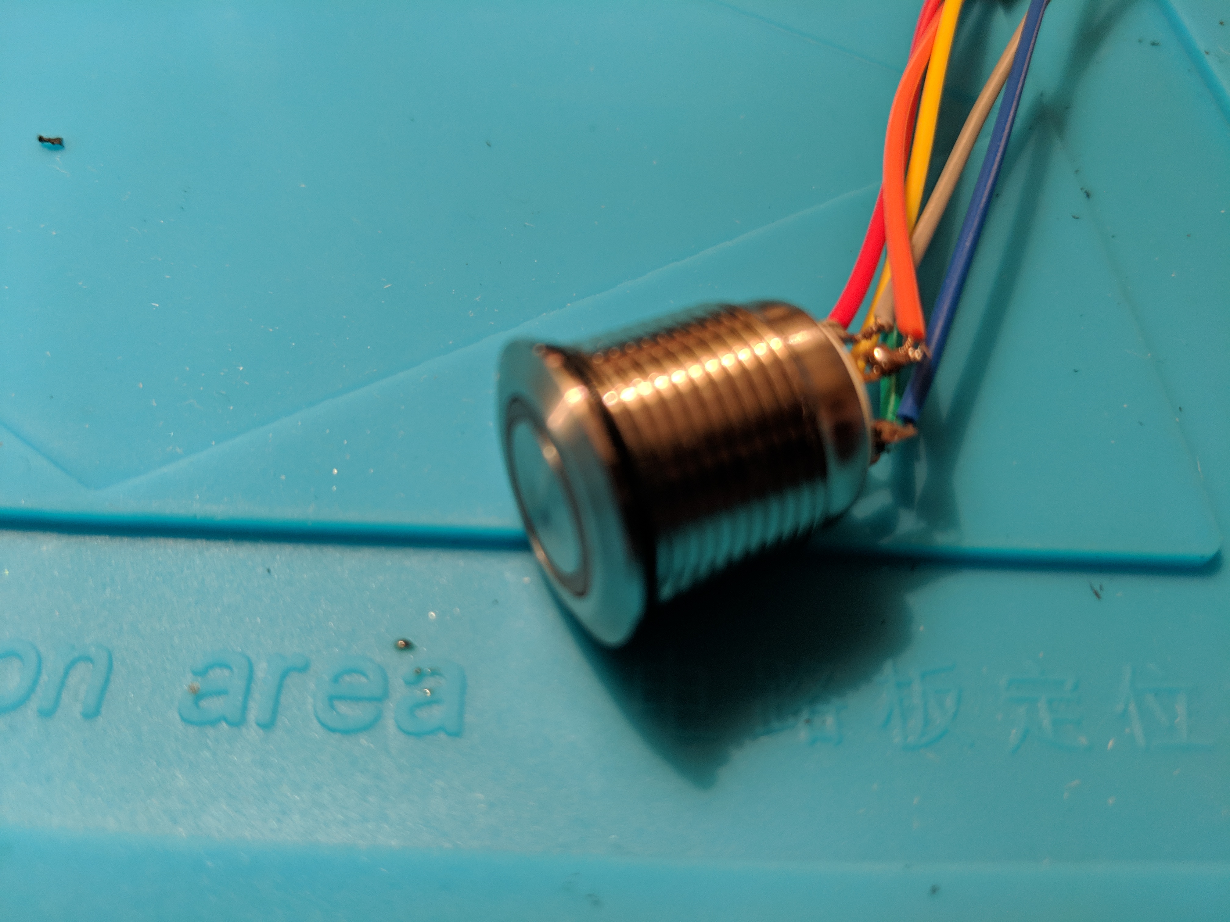
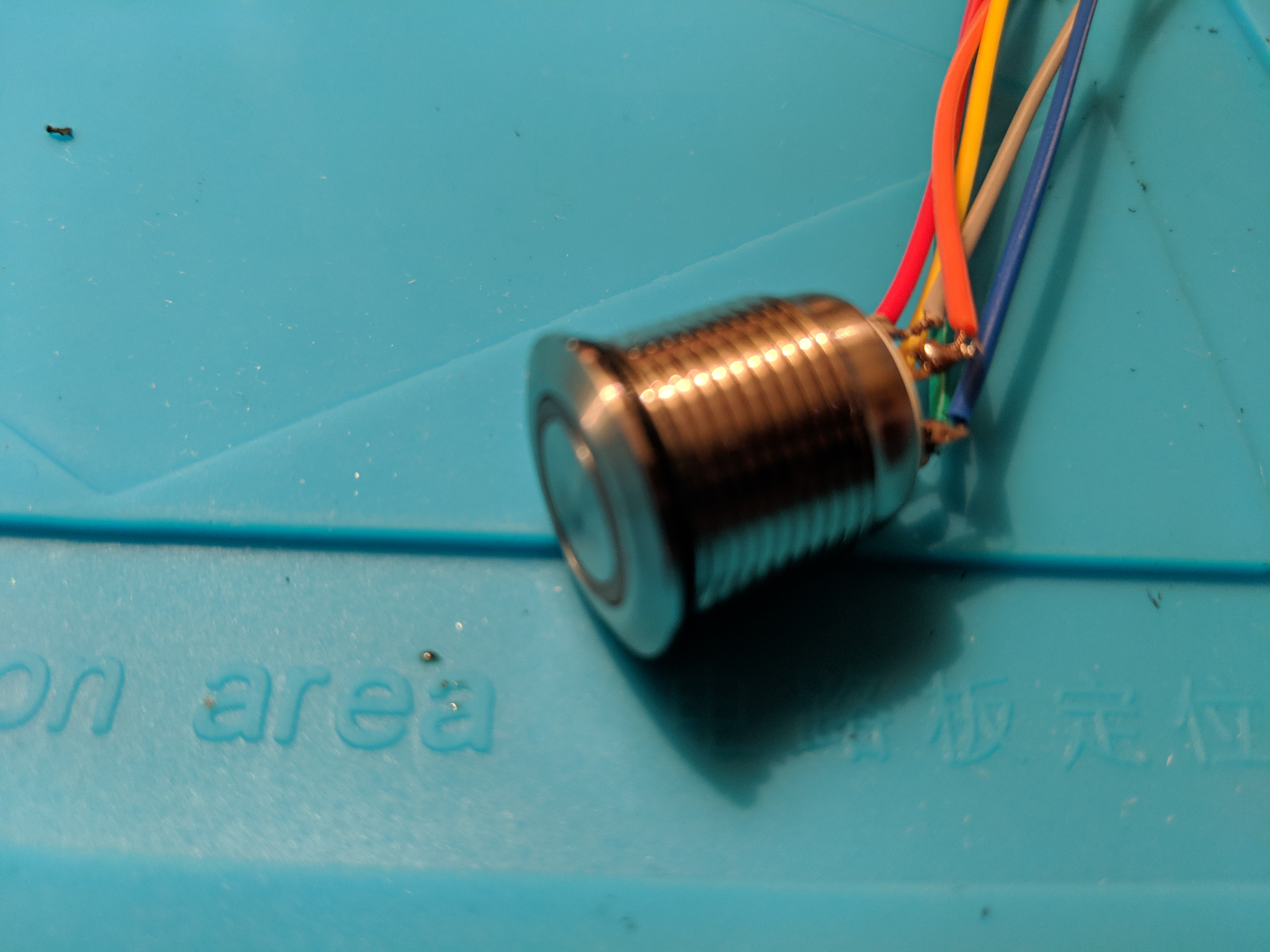
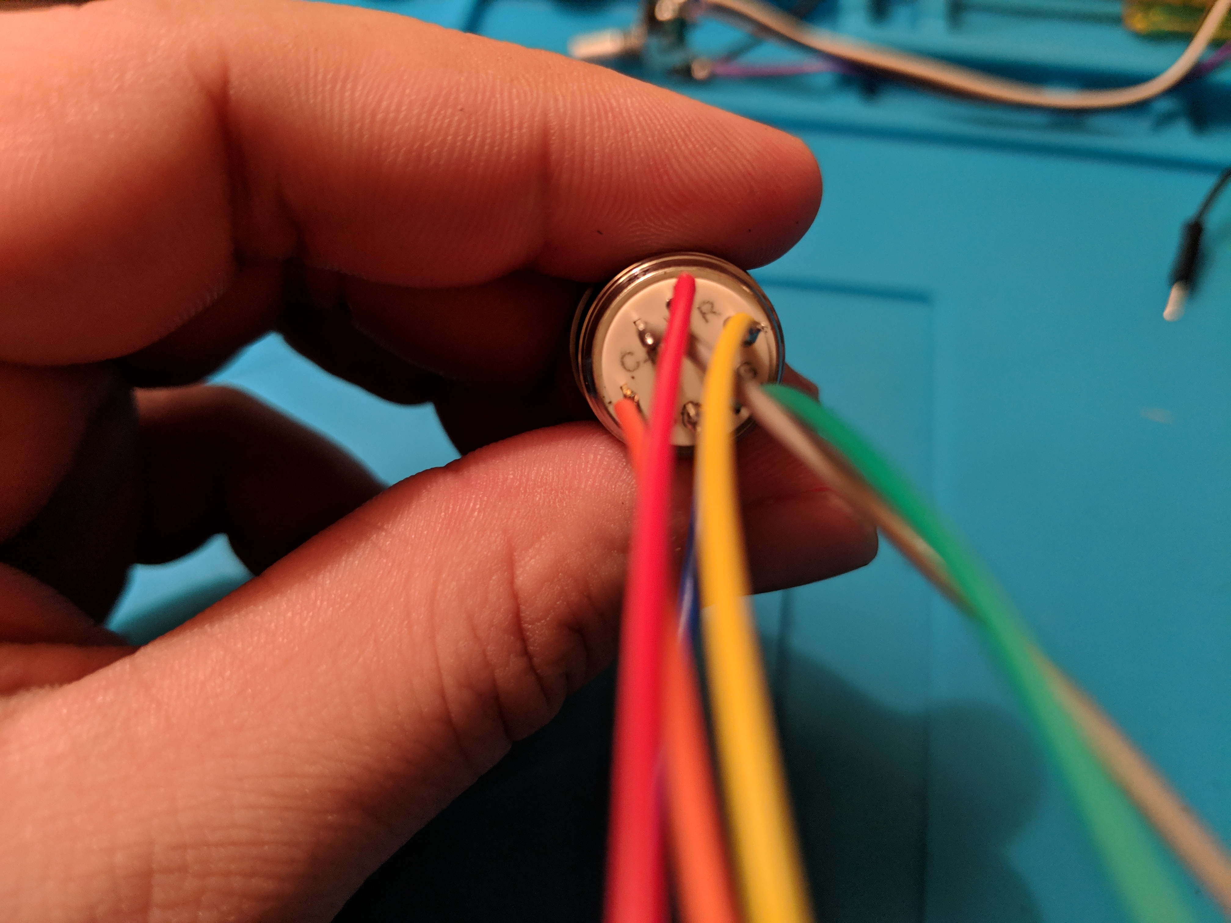
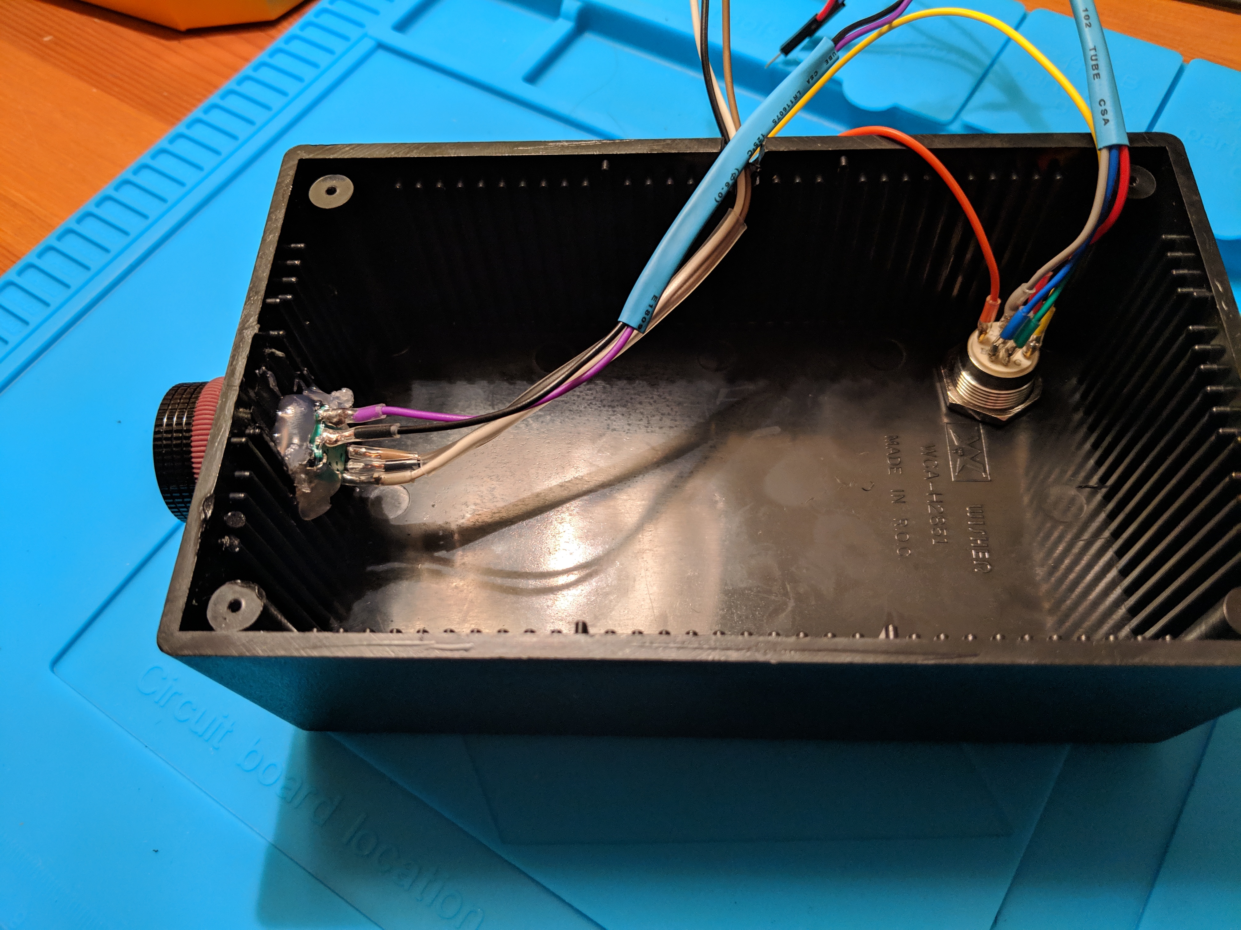
The button has a RGB LED in it so I color coded the wires. Red for the red channel, green for the green, and blue for the blue. The yellow and orange are for the button itself.
During the week, a heat gun I had ordered arrived so I slipped some
plastic shrink around all of my soldered connections and then larger
ones to group the wires together a bit.
Thanks to some advice from a friend, I picked up some heat resistant
gloves on Amazon and didn’t burn myself with the heat gun at all.
With all the wires soldered in place. I just have to assemble
everything again. I screwed in the button, and glued in the encoder.
Then I remembered that the encoder had a bolt as well, so I attached
that and it was much more secure.
I upgraded the knob on the encoder to a nice metal 1” job from Adafruit. It has a nice feel to it. Just needed a 2mm hex wrench to secure it in place. Which I got today, just in time.
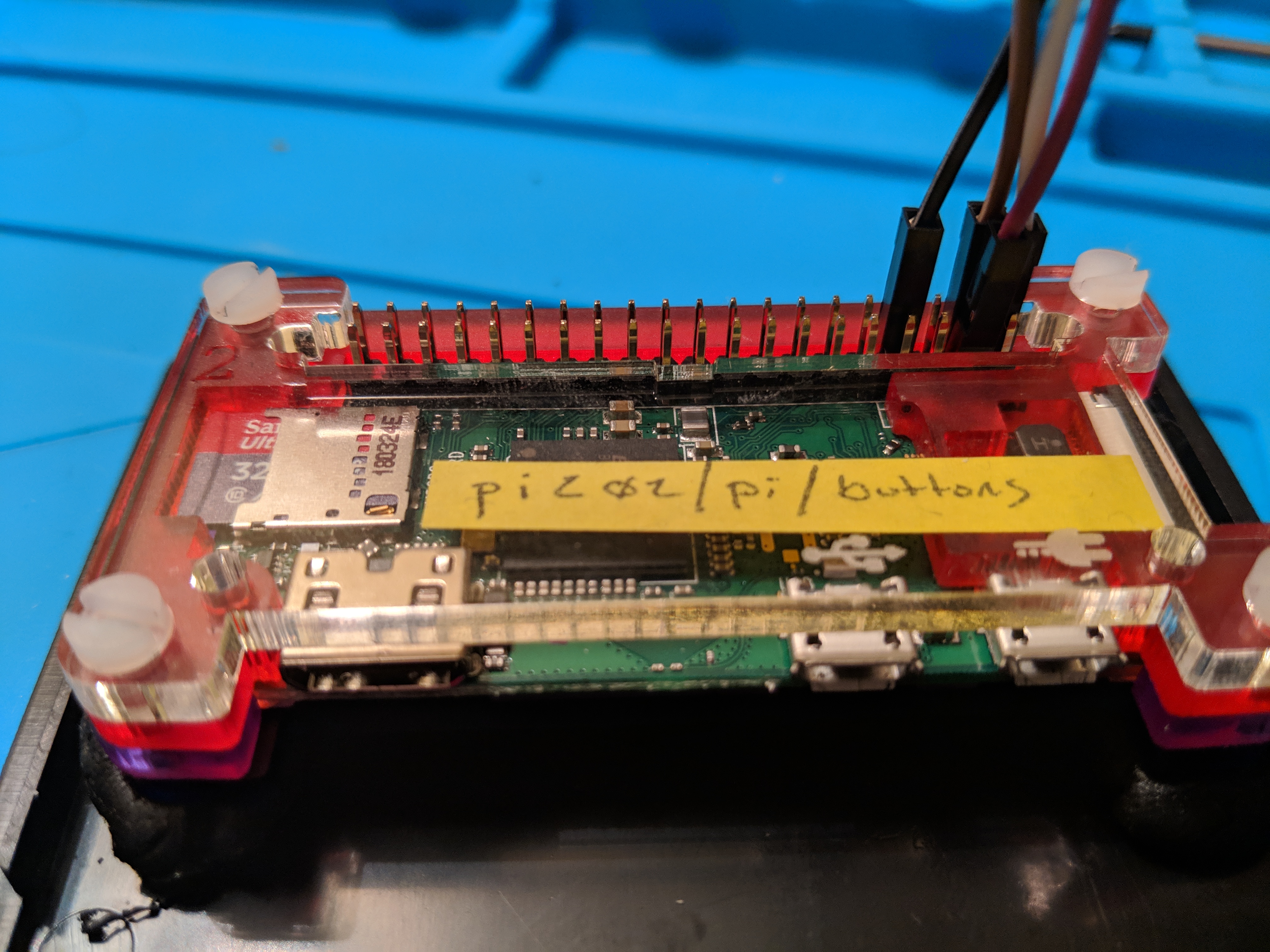
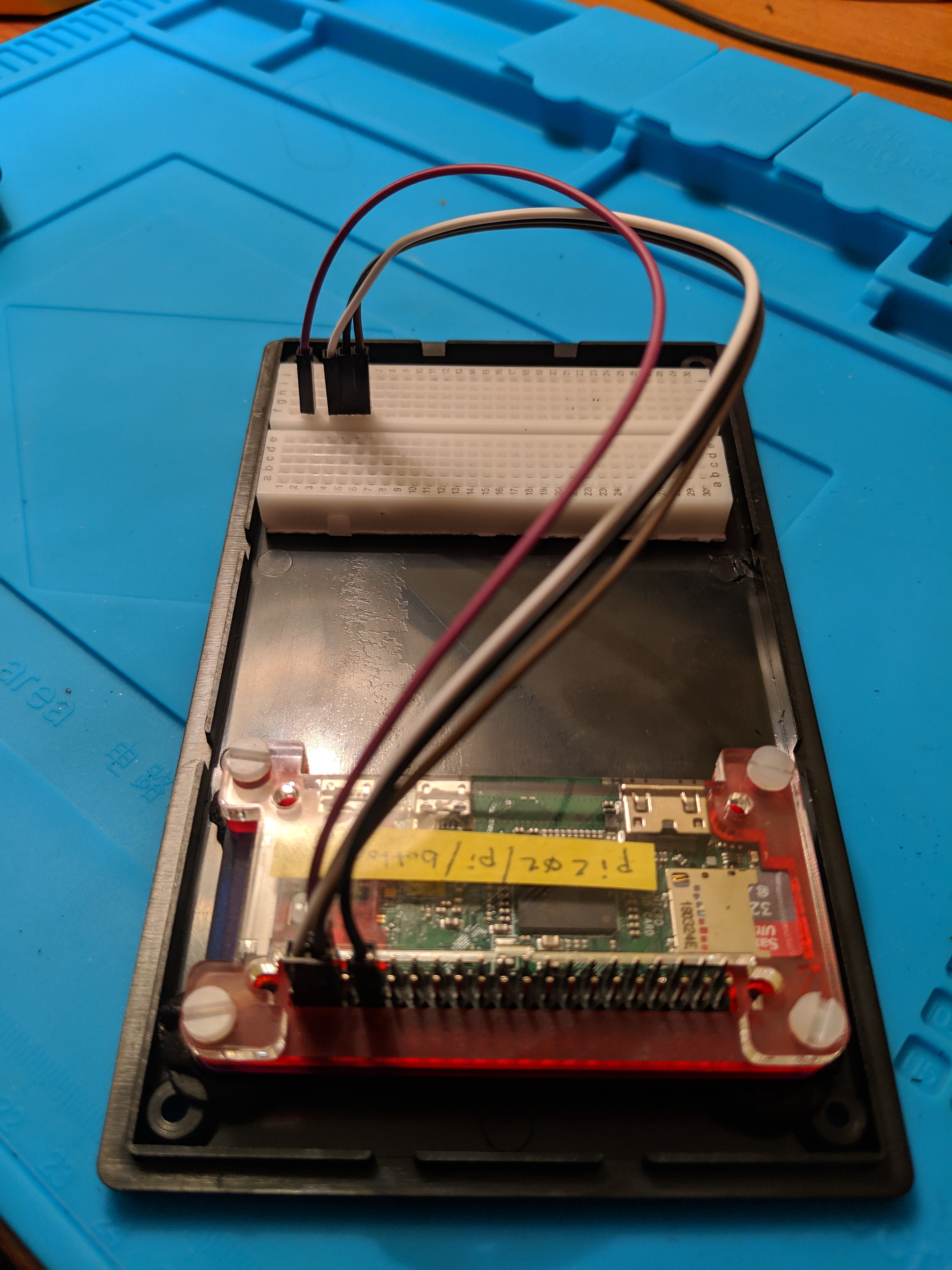
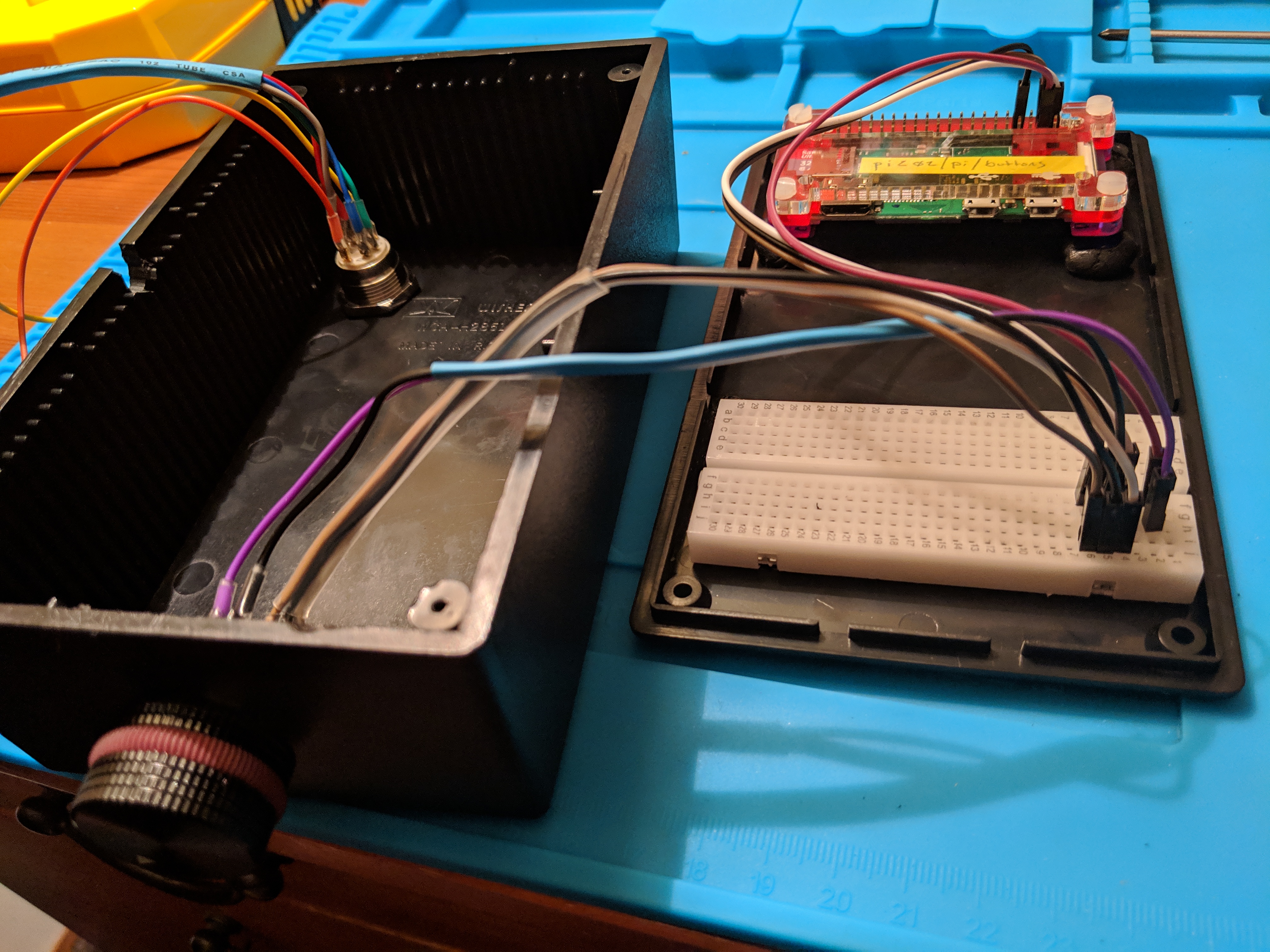
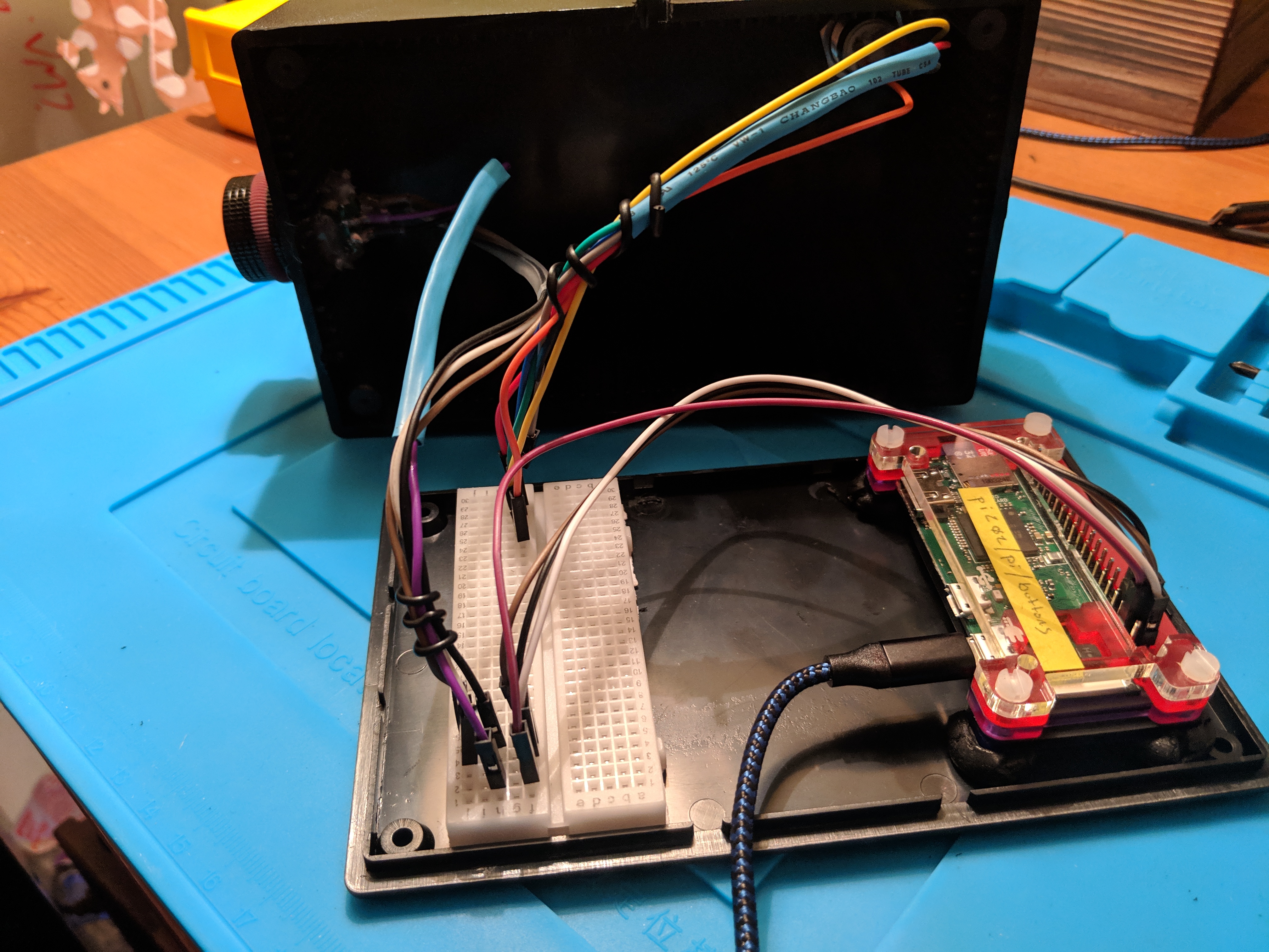
Now that the Sugru has had enough time to set, I reassembled the Pi
case . . .
. . . and plugged it into the breadboard.
I had color coordinated the wires for the Pi with the rotary
encoder, so it was easy to remember what goes where.
For now, I’m plugging the power button in randomly to the breadboard
just so the wires aren’t loose. My next step is to get that bit
working.
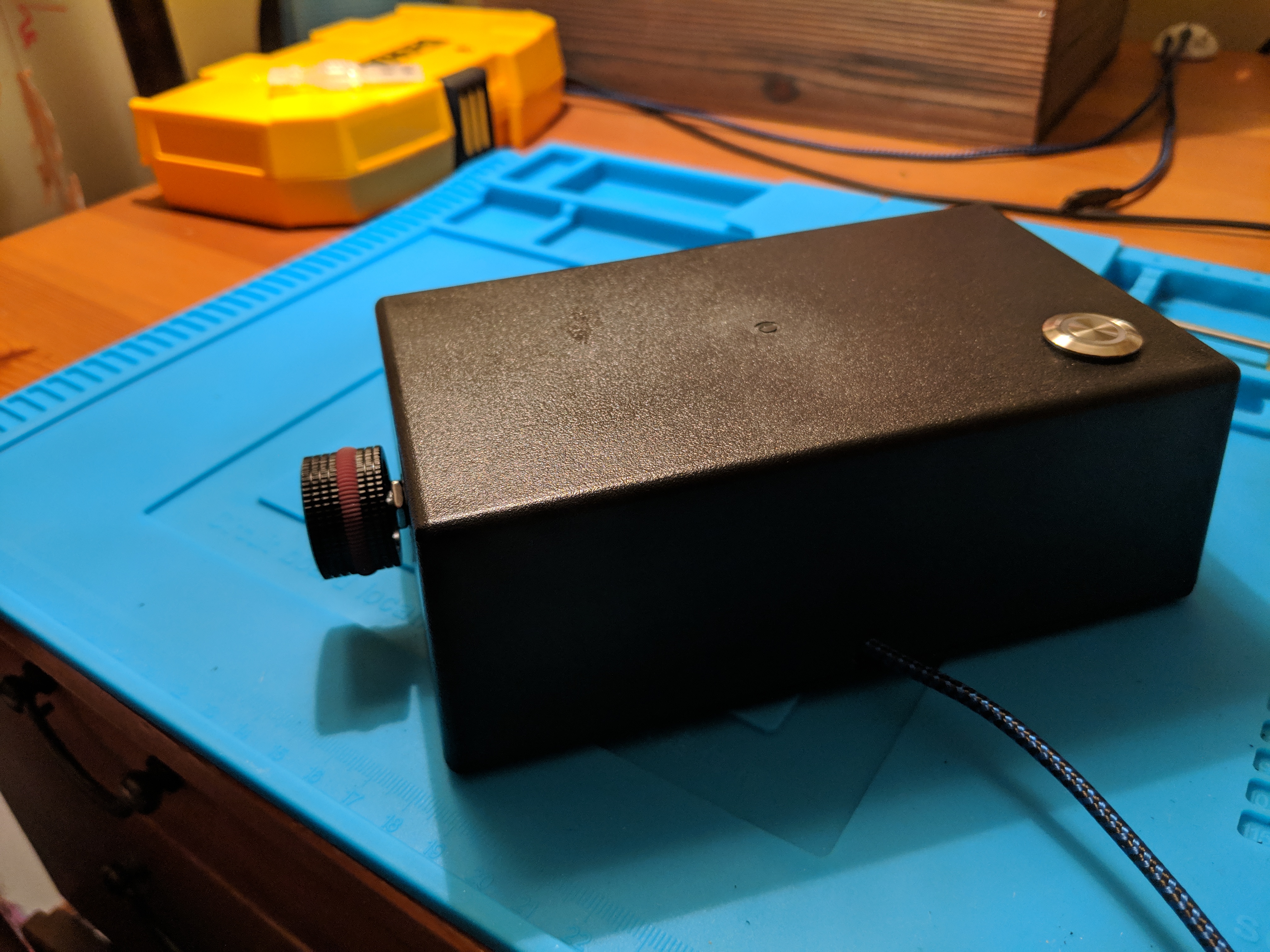
And voila.
I was surprised by home much I was able to get done in one day. It
still doesn’t really do much except call a webservice that just logs
that it was called, but it’s a start.