
RGB LEDs on Pi with Adafruit 12 Channel 16 Bit PWM LED Driver
Here are some quick notes on getting the 12 channel 16-bit PWM driver from Adafruit. (It’s not that different from the 24 channel version) As usual, Adafruit’s documentation was super useful, and they even had a page about getting it to work with the pi.
What is a PWM Driver?
A Pulse Width Modulation driver allows you to either connect a whole bunch of regular LEDs with just a few pins (and the PSI protocol). The 12 channel driver can support 12 LEDs. Additional drivers can be daisy chained on allowing near limitless LEDs. If regular LEDs don’t interest you, you can use 3 channels to drive a single RGB LED (for 4 total per module).
Software Setup
- Enable SPI. (
- Run
sudo vim /boot/config.txt - Ensure
dtparam=spi=onis uncommented (or add it) - Reboot with
sudo reboot - Verify it worked with
ls /dev/spi*
- Run
- Python Dependencies
- Install python-venv with
sudo apt-get install python3-venv - Install pip with
sudo apt-get install python3-pip - Create a virtual environment for your project with
python3 -m venv pvenv
- Install python-venv with
- Install Circuit Python on the Pi
- Install Circuit Python with
pip3 install adafruit-blinka - Install the Adafruit library
pip3 install adafruit-circuitpython-tlc59711 - Verify everything works by going into the python interpreter and importing the new packages (you shouldn’t get any errors)
 import board
 import busio
 import digitalio
 import adafruit_tlc59711
- Install Circuit Python with
- Optionally save your imports with
pip3 freeze > requirements.txt
Hardware Setup
- Optionally follow the instructions on Adafruit’s site to solder on headers so the module can be plugged into a breadboard.
- Optionally solder on headers to the voltage pins on the board. This helps wiring when it’s inconvenient to just wire the LED’s leg directly to power.
- Wire it up! Use the below table or image. Make sure that you orient the board correctly and that you’re plugging into the input side and not the output side
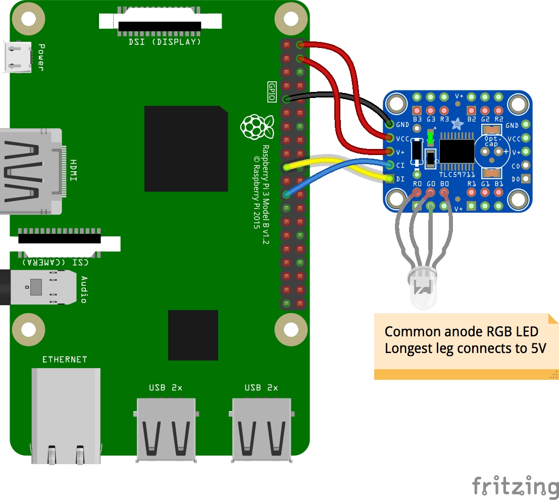
The table goes from the top down on the pins on the left side of the module. When there are multiple pins to choose from, I have bolded the pin that I used.
| PWM (TLC59711) | Raspberry Pi | Pi Pin Number |
|---|---|---|
| GND | Ground | 6, 9, 14, 20, 25, 30, 34, or 39 |
| VCC | 5v Power | 2 or 4 |
| V+ | 5v Power | 2 or 4 |
| CI | Serial Clock (SLK) | 17 |
| DI | MOSI | 19 |
After this, plug an RGB LED in to any of the RGB pins on the board with the longest pin going to one of the 12 voltage pins.
Testing it
Fire up a python3 REPL and import everything from above and then start turning on some LEDS:
import board
import busio
import digitalio
import adafruit_tlc59711

spi = busio.SPI(clock=board.SCK, MOSI=board.MOSI)
rgb = adafruit_tlc59711.TLC59711(spi)

# Full Red, Green, or Blue (mix/match as much as you like)
rgb[1] = (65535, 0, 0)
rgb[1] = (0, 65535, 0)
rgb[1] = (0, 0, 65535)

rgb.b1 = 32768
rgb.g1 = 16384
rgb.r1 = 8192

rgb.red_brightness = 10
rgb.green_brightness = 10
rgb.blue_brightness = 10