
Pi Project Status Report Day 4.5
Not only am I late with this status report for last Sunday. I finished getting everything wired up and cleaned up my desk with 3 minutes to spare before the season premier of Game of Thrones. There was no chance I was going to write up a status report at that point. Since then I’ve done more work so it’s not really a true status for day 4. Let’s call it 4.5.
Software
I decided to shelve any work towards getting the BlueTooth connectivity to work for the time being. I was putting a lot of effort into that without a lot of results. My goal for an MVP is now to get a box that has a volume knob that works. The quickest route without too much throwaway work is a device that makes rest calls to a configured laptop running a webservice that handles the volume control. This will let me concentrate on getting the electronics up and running and the physical box built.
Towards that, the first thing I did was refactor out the SimpleButon and SimpleRotary scripts I had from last week into python classes and use them in a python script that calls a webservice.
With that done, I quickly transferred the proof of concept to a Pi
Zero W. Or at least I tried to. For whatever reason, whenever I
tried to do a git pull the command line hung. After some googling
I tried a last ditch attempt of just updating the OS with
sudo apt-get update
sudo apt-get dist-upgrade
Surprisingly, that actually did the trick. Now my only issue is that I never installed the prereqs on the Zeros. So a few apt-gets later, and I’m back in business.
sudo apt-get -y install python3-rpi.gpio
sudo apt-get -y install python3-venv
Once the code’s running on the Pi, I have to figure out how to get it to run whenever it stats. Some more googling and I find Pi’s documentation on rc.local.
sudo vim /etc/rc.local
Hardware
Coding. Done. Linux administration. Done. Next up is actually making the box.
A few weeks ago I picked up a black plastic enclosure from Tinkersphere. To make it easy to expand in the future, I used the glue backing on the back of an extra mini breadboard to affix it to the bottom of the case. I had to take the power rails off first so it would fit in the slot.
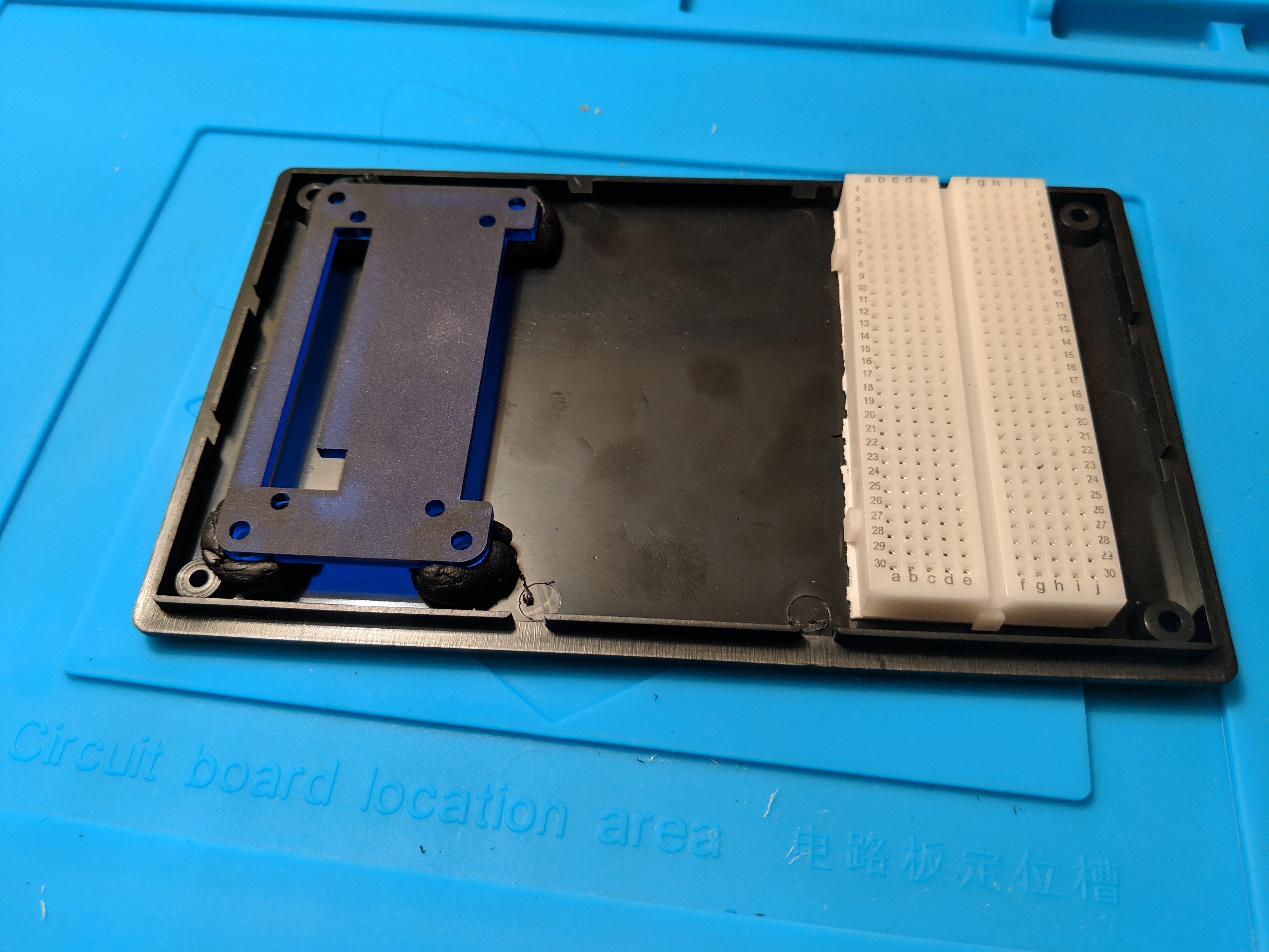
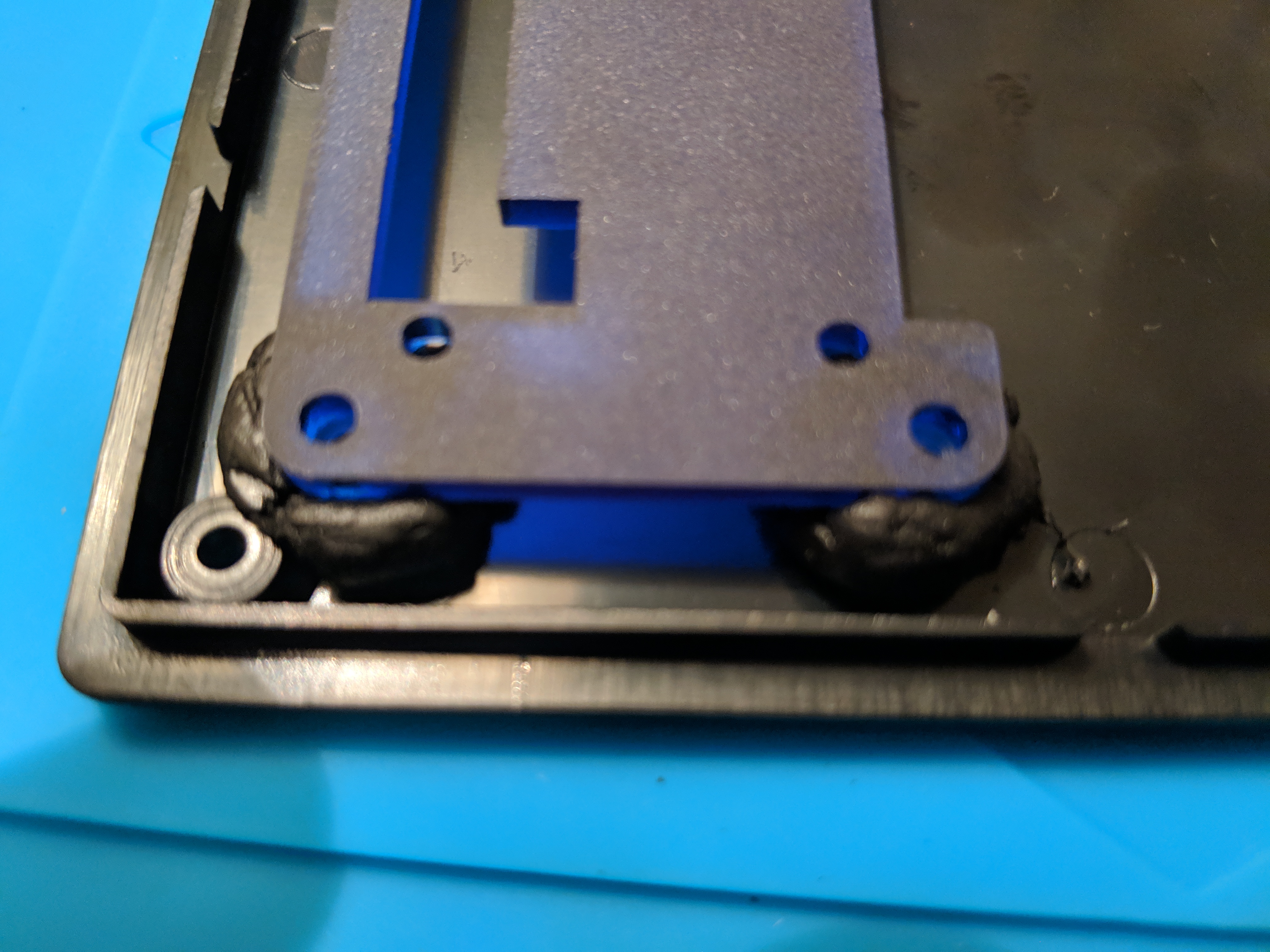
Next, I use Sugru on the bolts of my PiBow case to affix it to case. I used the full assembled case to ensure that there was sufficient space for the bolts, but removed disassembled the case and left only the bottom plate and the bolts while it set. I’m actually pretty surprised it worked so well.
The Sugru is solid enough that it didn’t ooze anywhere it wasn’t supposed to. I kind of want to try the same thing with a glue gun since it’s a little cheaper and easier to have on hand (my Sugru was technically expired…). I just don’t think it’ll work as well.
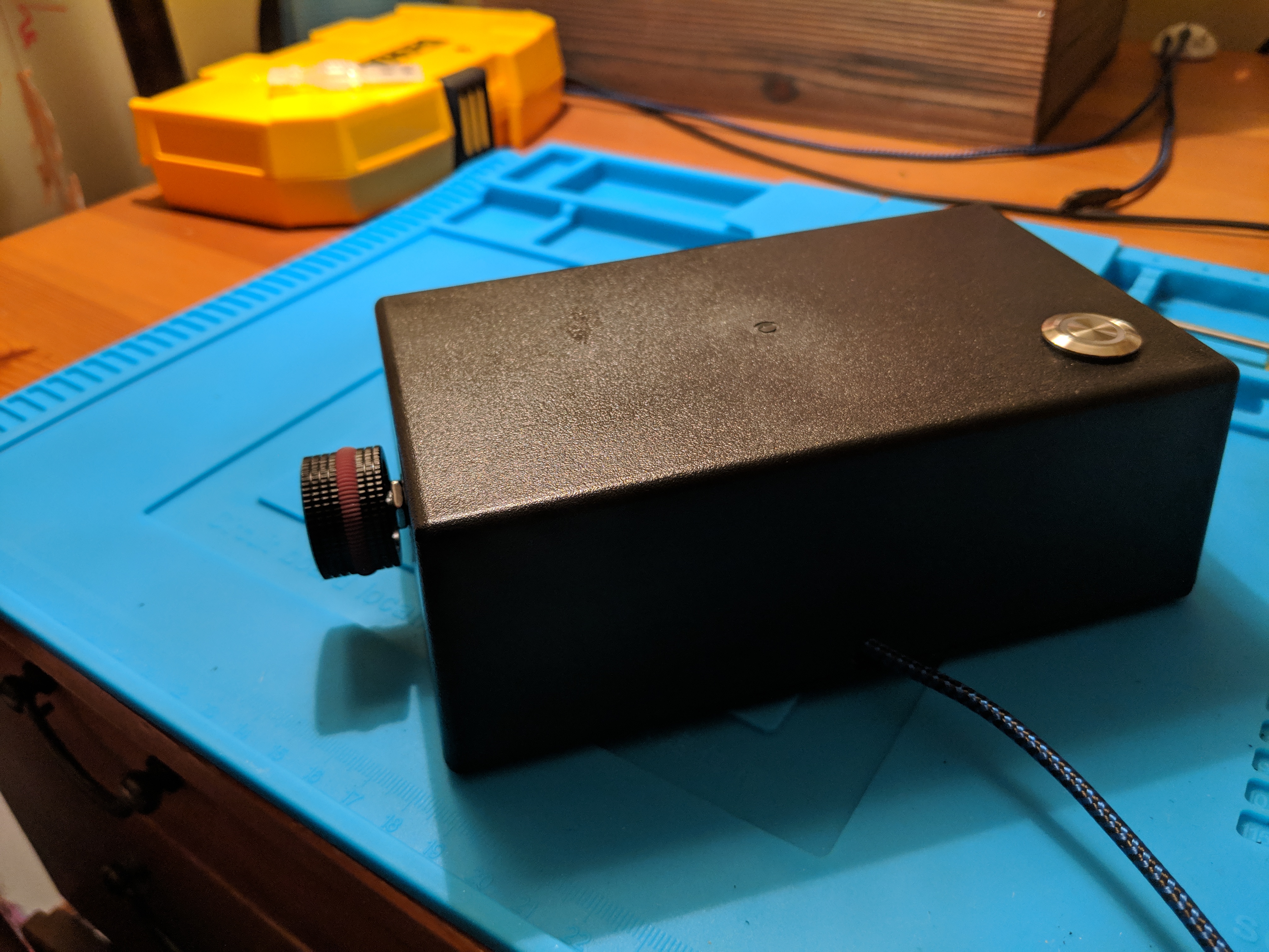
Now on to the top. I used a 15mm Forstner bit to drill a hole in the top for the power button. Then I used a 16mm bit to widen it because I misread the size on the button.
I used standard drill bits to make a 5/16” hole in the side for the rotary encoder. This time I started with a quarter inch bit on Sunday, and then had to buy the 5/16” bit during the week. It was a perfect fit with the additional 1/16” inch.
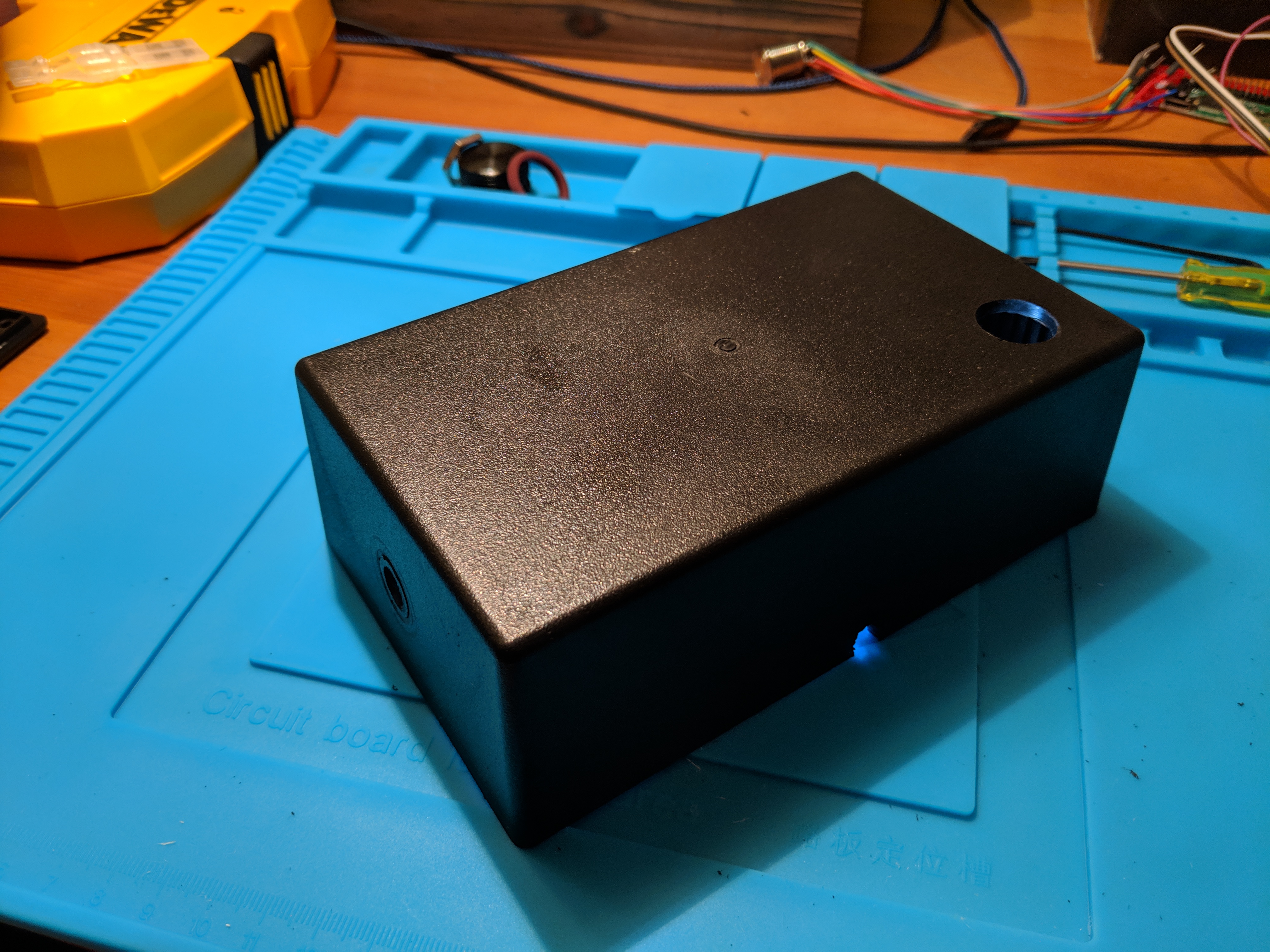
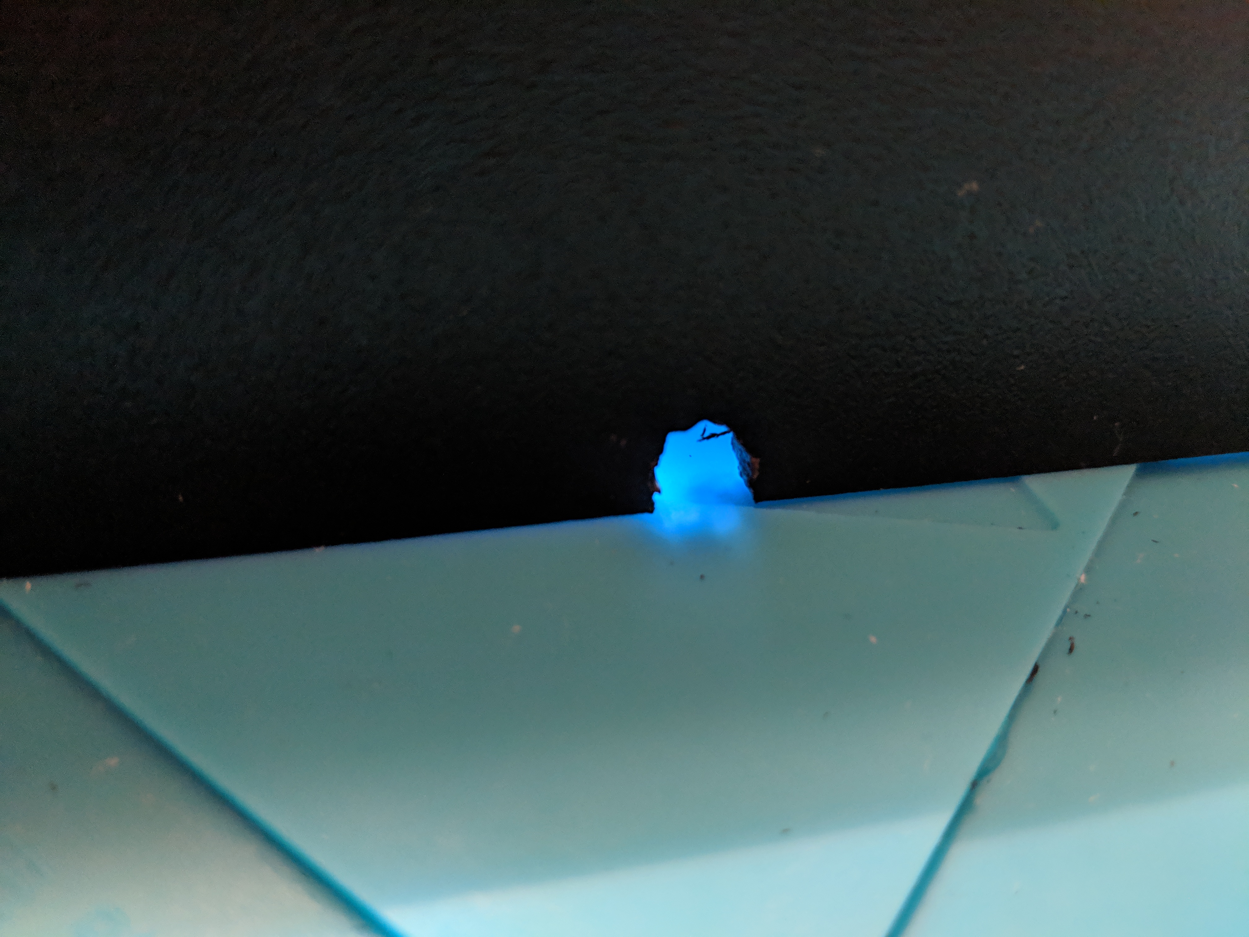
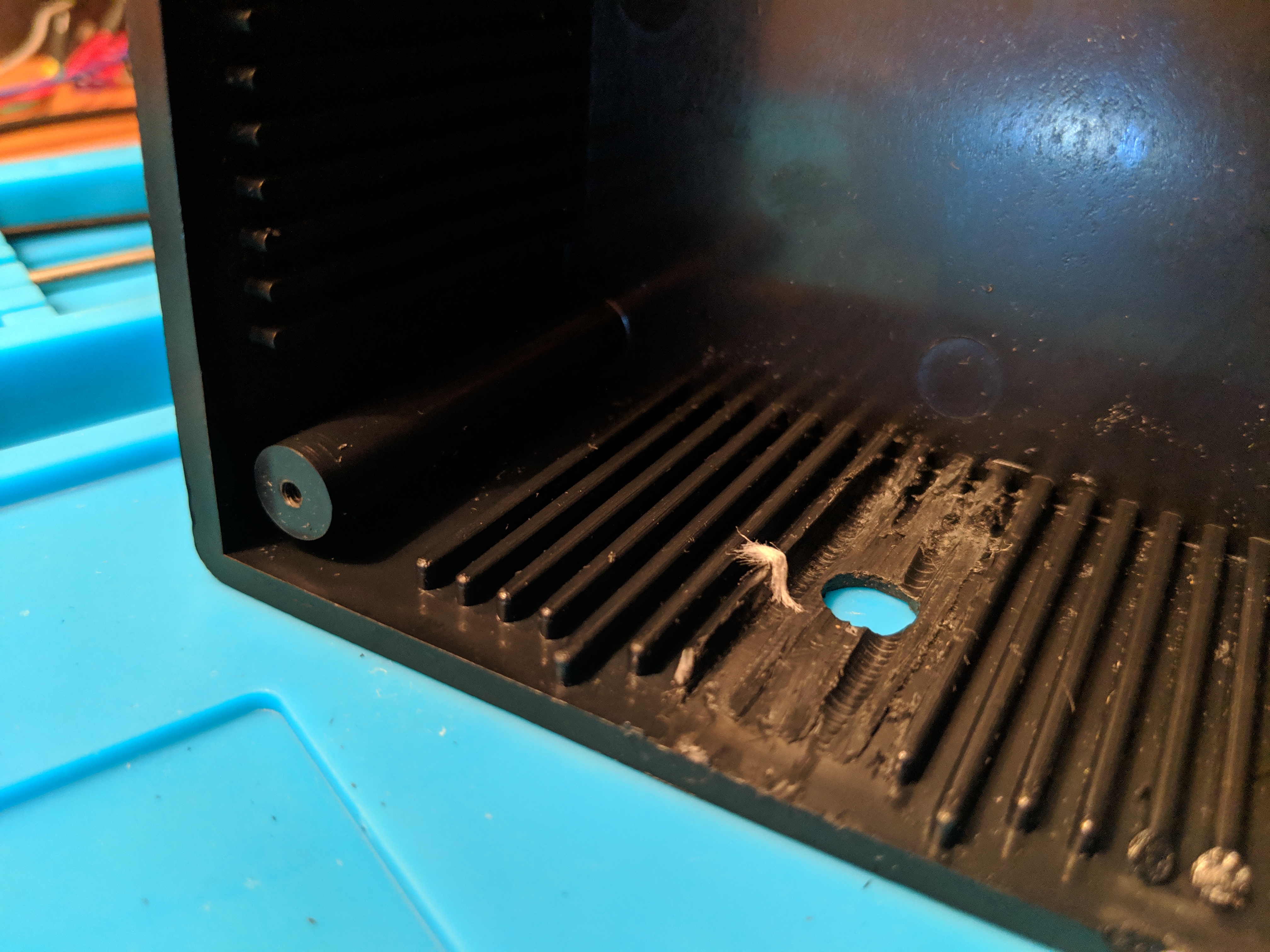
I couldn’t figure out how to cleanly get a small hole for the power USB cable in the bottom of the case. I went drilling a hole near the edge and then using my Leatherman to whittle the notch to the desired size. Worked well enough, but it wasn’t as smooth as the other holes.
I needed to get rid of the ridges on the interior side for the encoder to sit flush and extend far enough out. I didn’t have any better ideas so I grabbed a drill bit a little larger than the space between the grooves. I used that to drill out some of the ridges and then went in with the blade of my Leatherman to remove the rest. Next the file on the Leatherman helped smooth out any uneven ridges. Not super pretty, but it worked; the encoder sat flush.
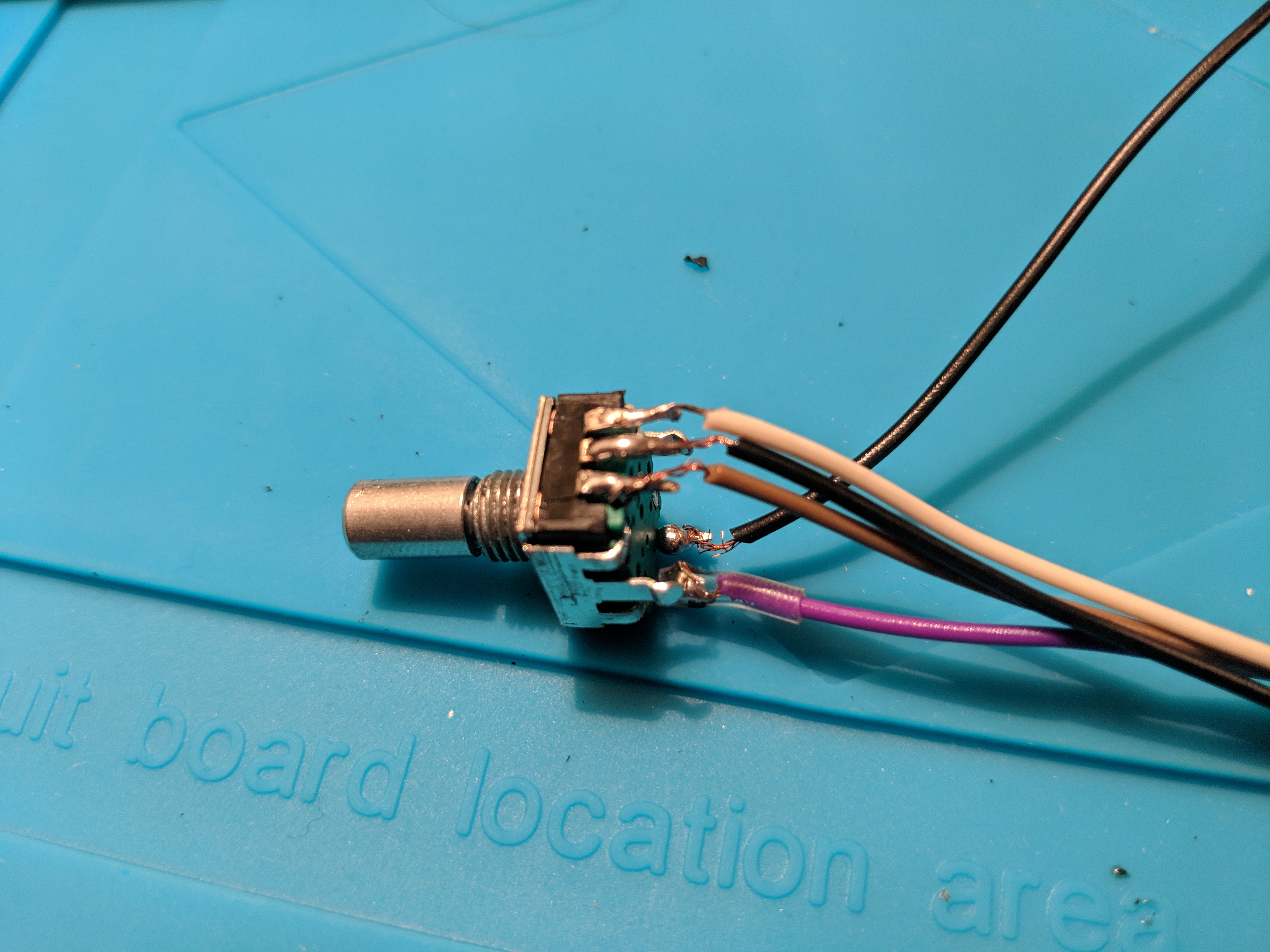
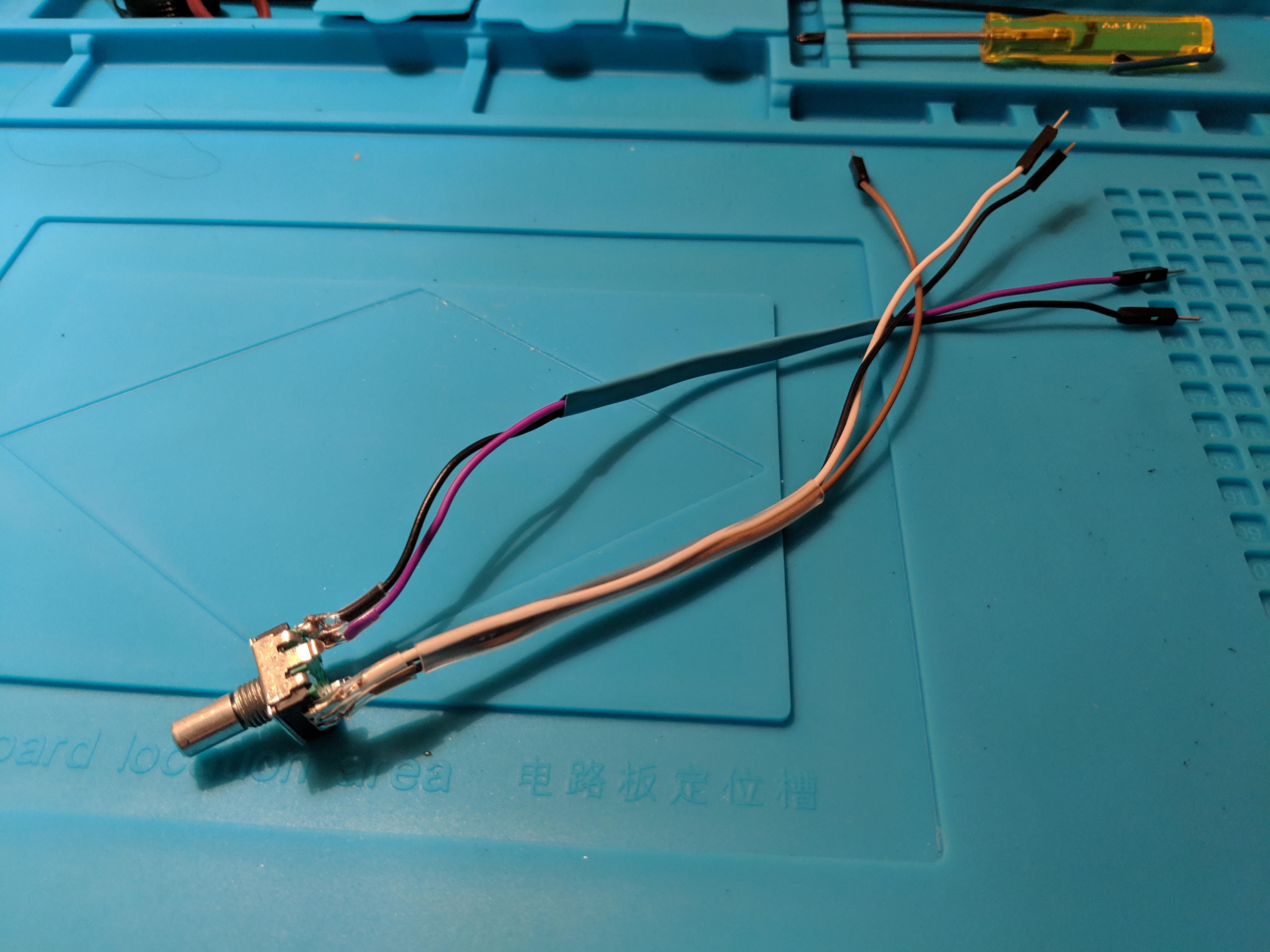
Speaking of the encoder, I was concerned about how I was going to attach the wires to it in reliable way. I didn’t have any better ideas, so I figured now was a good enough time as any to learn how to solder.
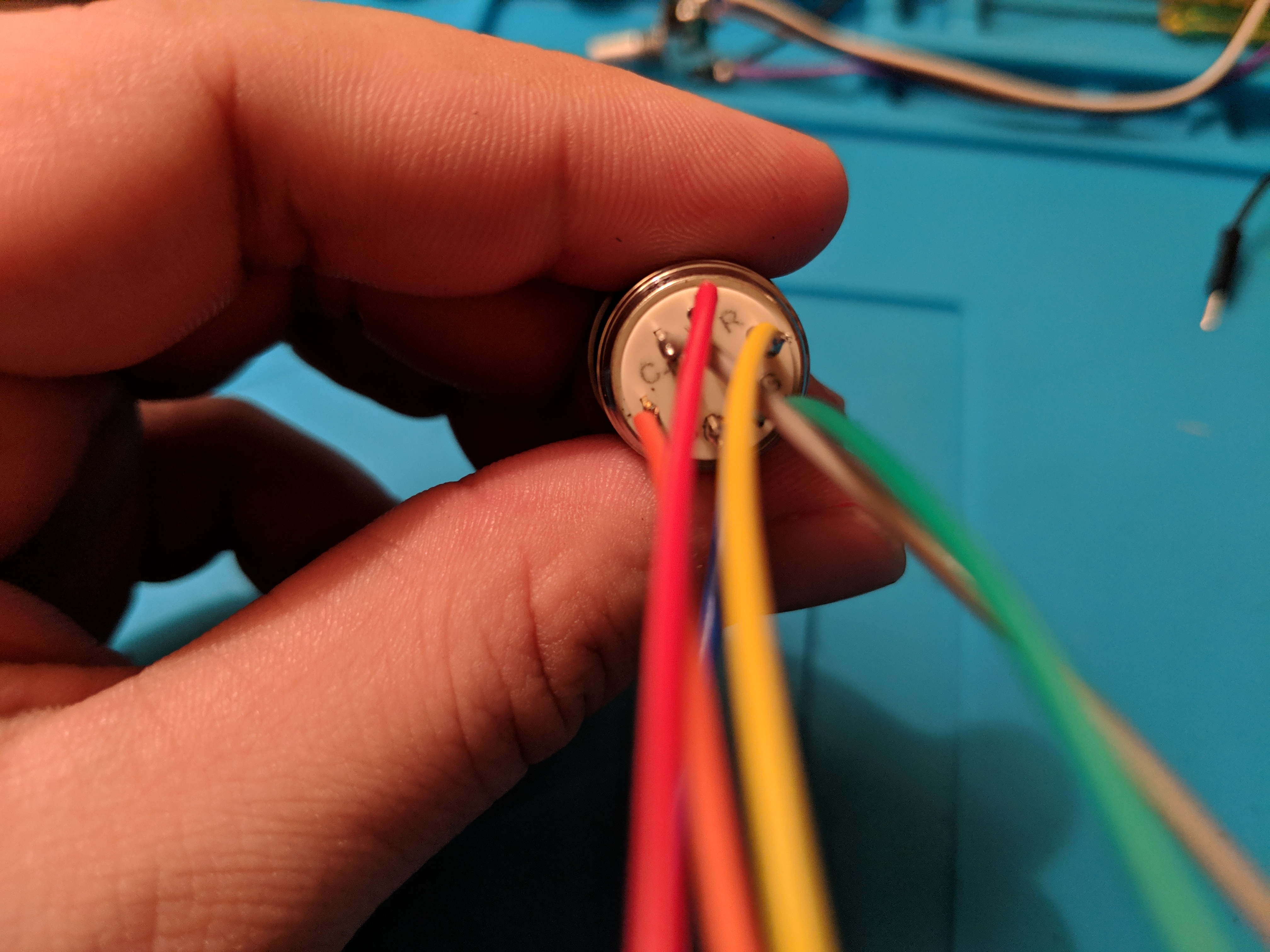
Including burning myself (twice), it went much better than I expected. I cut off one end of some jumper wires and soldered them on to the encoder and then button. I was on such a roll I even soldered the head on to a TLC5947 from Adafruit. I plan on using that in my next step to power the RGB light ring on the button.

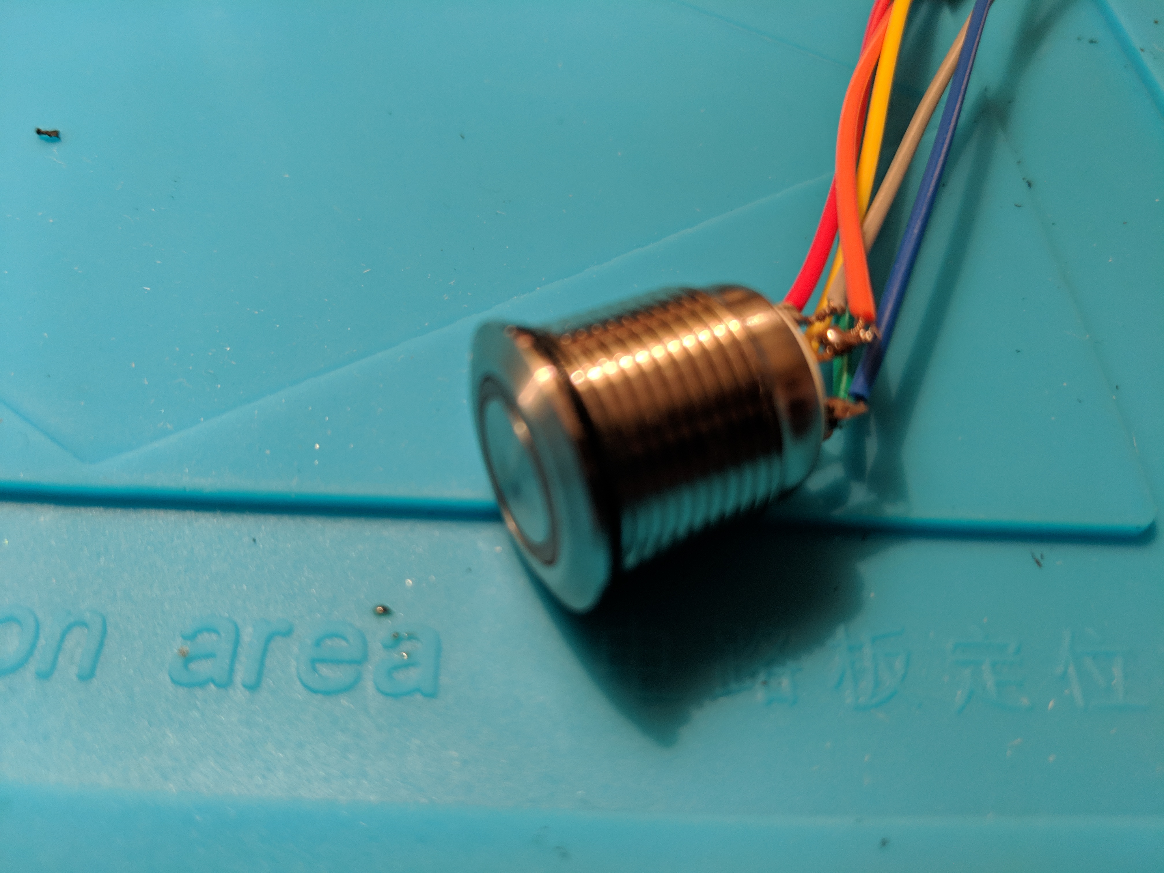
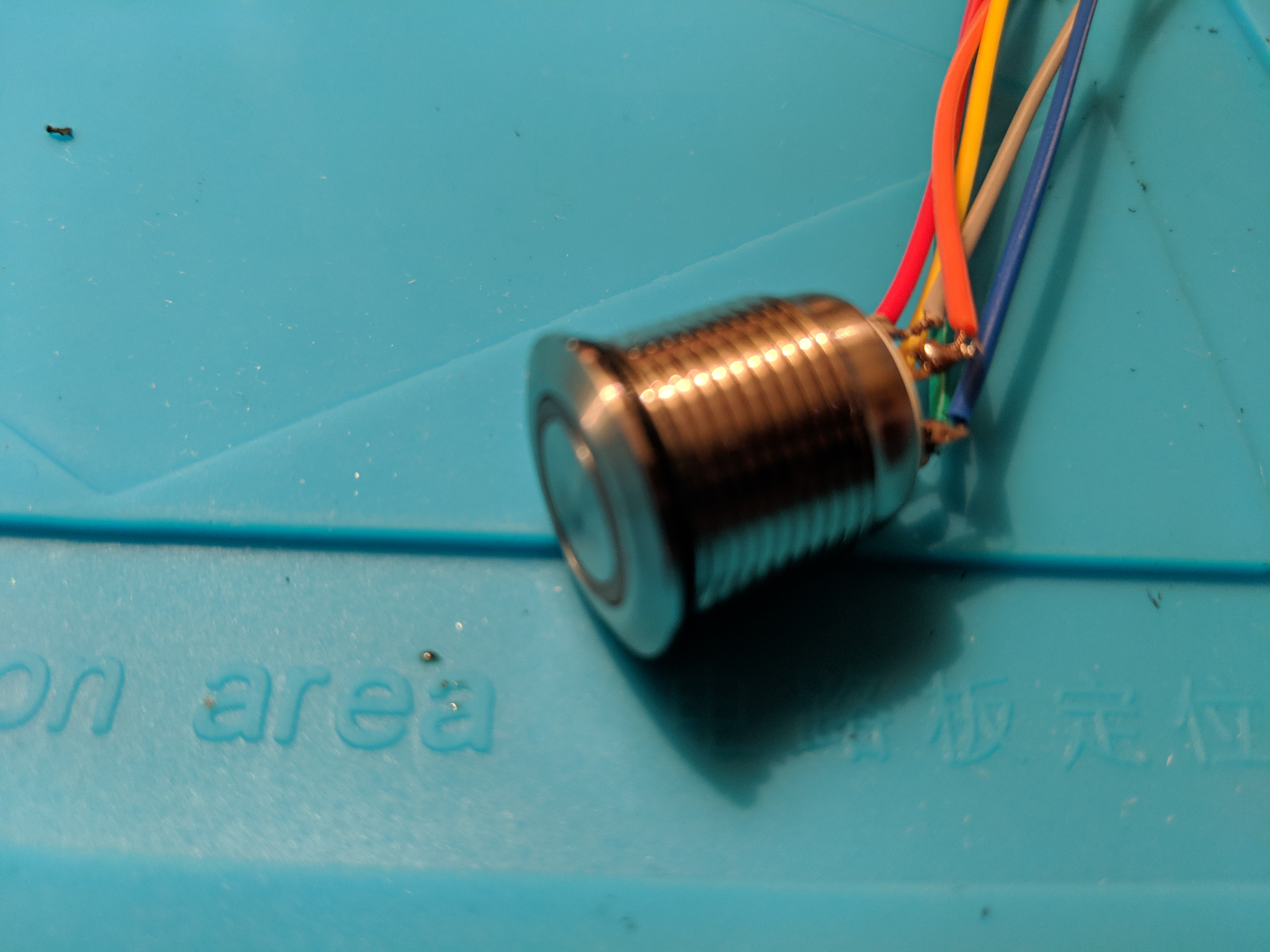
The button has a RGB LED in it so I color coded the wires. Red for the red channel, green for the green, and blue for the blue. The yellow and orange are for the button itself.
During the week, a heat gun I had ordered arrived so I slipped some plastic shrink around all of my soldered connections and then larger ones to group the wires together a bit.
Thanks to some advice from a friend, I picked up some heat resistant gloves on Amazon and didn’t burn myself with the heat gun at all.
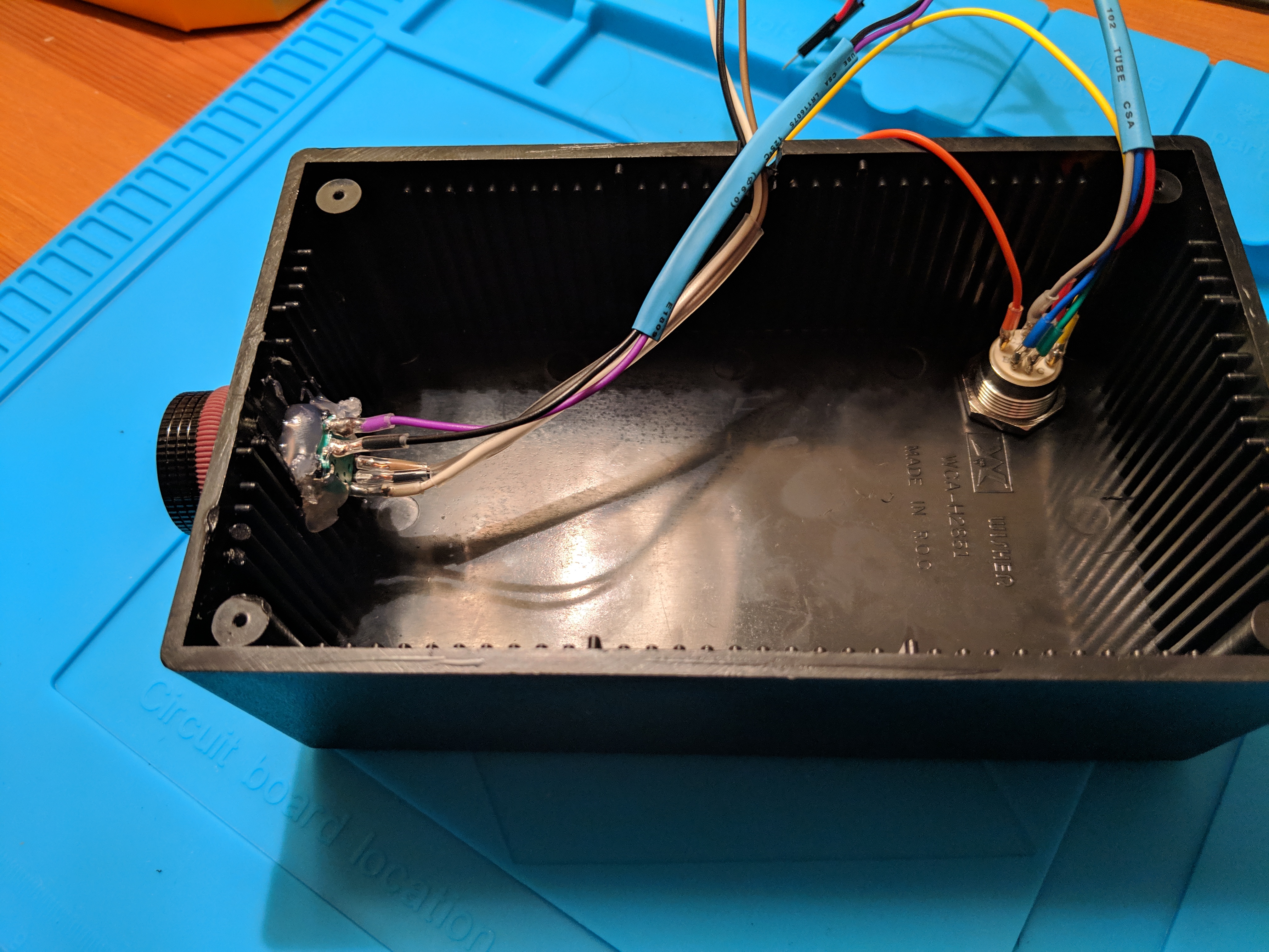
With all the wires soldered in place. I just have to assemble everything again. I screwed in the button, and glued in the encoder. Then I remembered that the encoder had a bolt as well, so I attached that and it was much more secure.
I upgraded the knob on the encoder to a nice metal 1” job from Adafruit. It has a nice feel to it. Just needed a 2mm hex wrench to secure it in place. Which I got today, just in time.
Now that the Sugru has had enough time to set, I reassembled the Pi case . . .
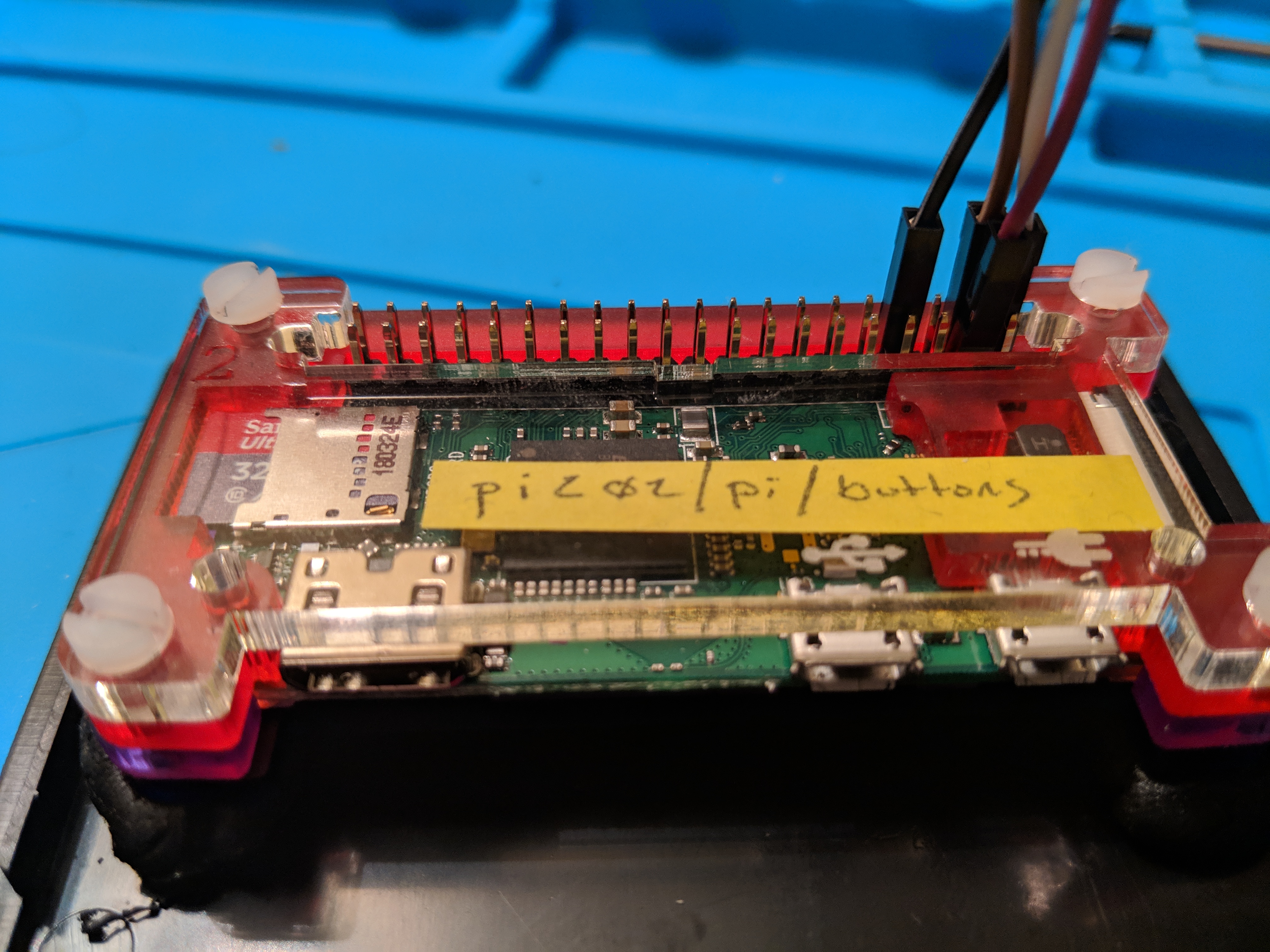
. . . and plugged it into the breadboard.
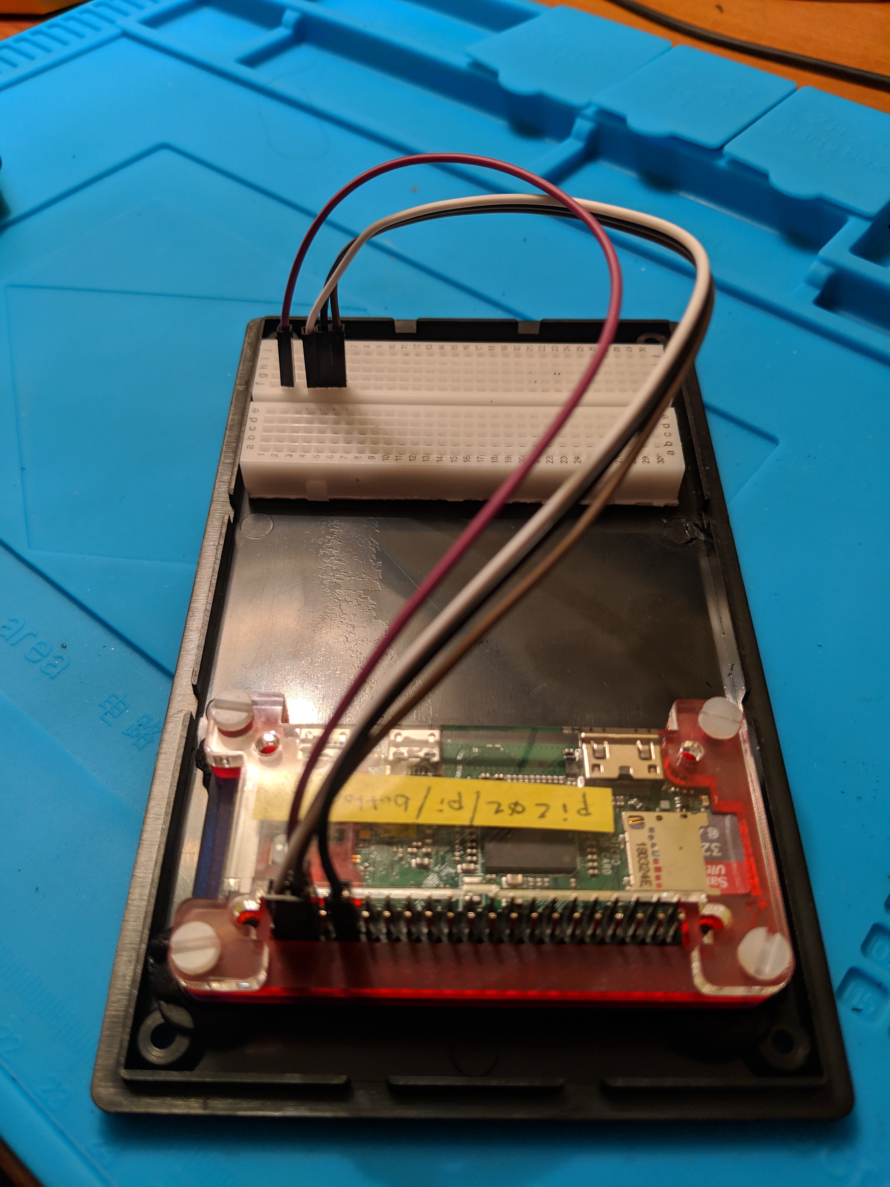
I had color coordinated the wires for the Pi with the rotary encoder, so it was easy to remember what goes where.
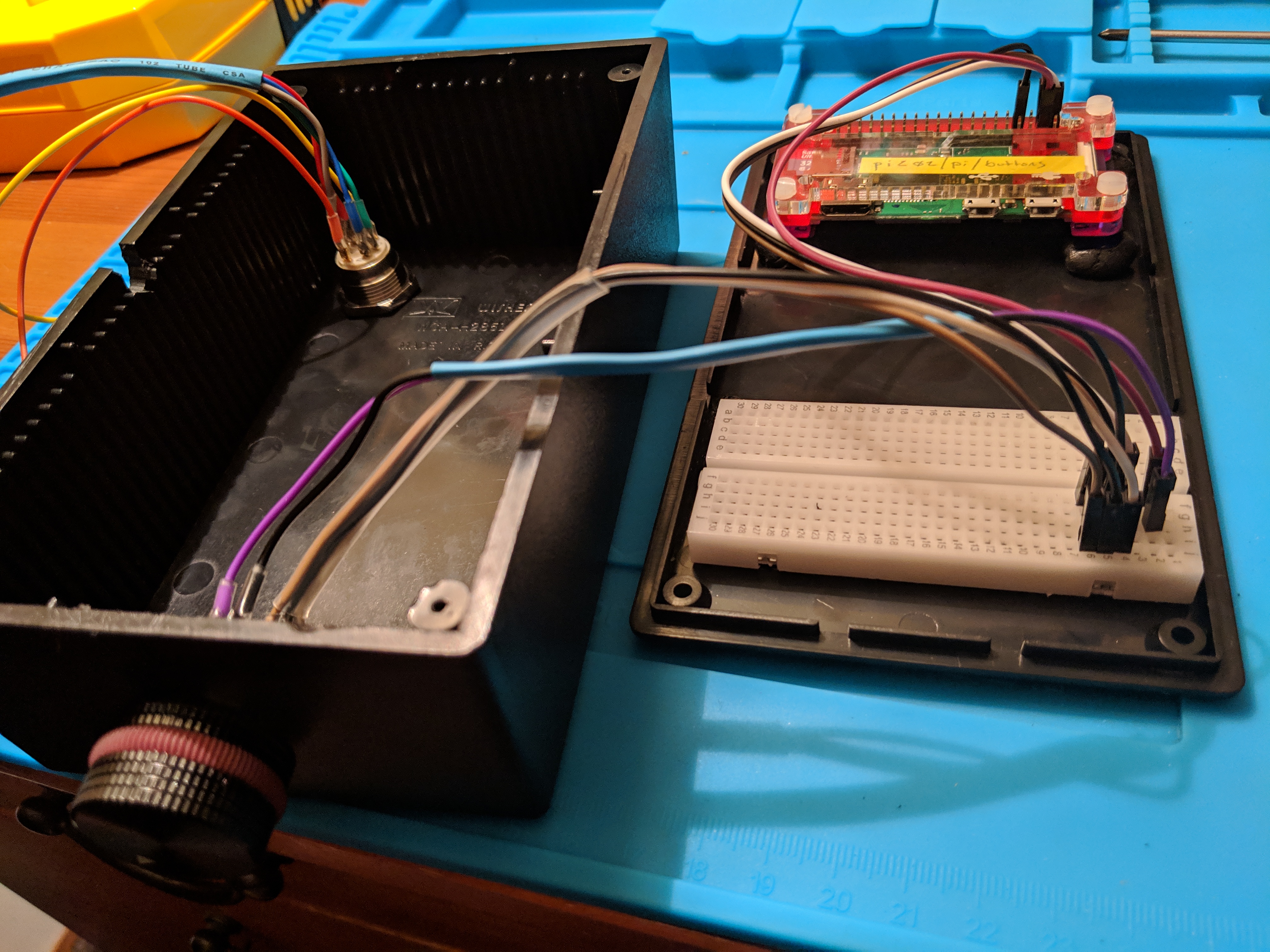
For now, I’m plugging the power button in randomly to the breadboard just so the wires aren’t loose. My next step is to get that bit working.
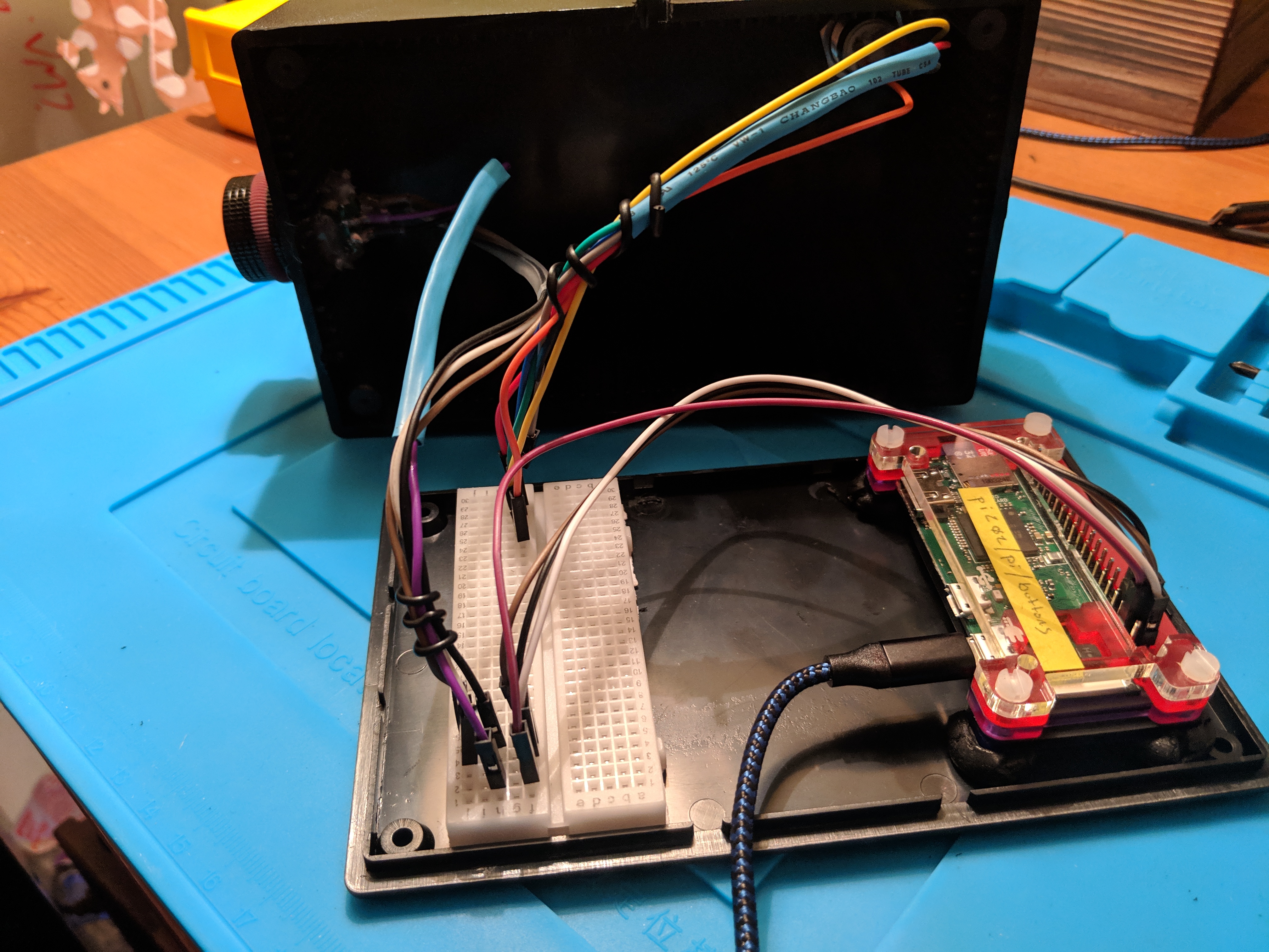
And voila.
I was surprised by home much I was able to get done in one day. It still doesn’t really do much except call a webservice that just logs that it was called, but it’s a start.
Here’s all the code on github as of this posting.