
Breadboard Computer 2 Registers
I’ve finished the registers for y project of building an 8-bit computer using TTL chips. I have built two general purpose registers (an “A register” and a “B register) as well as the instructor register for the computer. This step took a lot more time than the clock module. The main difficulties were cutting the wires to the correct size and then after that the thing just didn’t work. I couldn’t store or transfer any data.
What is a Register?
So what exactly did I build in the past few weeks? The computer I’m working on will have a certain amount of RAM to store information during the execution of a program. This information is both the data in the program as well as the program itself. For example, I can write a program that will add the numbers 2 and 4. The values 2 and 4 will be stored in RAM when the program is loaded into the computer. In addition to that, the program itself will be stored in memory. In a modern computer, the program would be stored on the hard drive, but it would eventually be loaded into RAM before it executes, and the data would probably be entered by a user. My computer won’t have either a hard drive or any form of user input. It will all just be stored directly in RAM.
Following the 2 plus 4 example, my computer can’t operate directly on the data in RAM. It can only add (or subtract) numbers that are stored in the registers. This means that we’ll need to copy the data from their location in RAM into either the A or B register. Once there the arithmetic-logic unit (the next part of the build) can operate on them. Basically, the register is short term storage for data being used very soon.
There are three operations you can do with a register:
- Write to it
- Read from it
- Clear it
Normally, you can’t easily inspect the data currently in the register. That would be boring and make it super hard to understand what’s going on at any given time in the computer. These registers have 8 red LED’s that will show the current state of the register.
Transferring data from one register to another (or to another part of the computer), that data is written and then read from the bus. The bus is pretty simple component that wires all the components together using 8 parallel input/outputs. Coordination is required so that only one thing is writing to the bus at a given time and that the component that wants that data is reading from it. For now that’s done manually, but wiring in that logic will be an important part of what makes this a computer.
Cutting Wires
Last time, I built the clock module for my 8-bit computer and I had a hell of a time cutting and stripping the wires just right. I could reliably cut the wires the right length, but then I couldn’t take off exactly 0.3” of insulation on either side using my strippers. I had two options: get good or buy more reliable strippers.
I went with the latter and picked up a set of Knipex wire strippers. These things are amazing. Set the length to strip, insert wire, pull trigger, repeat. The exact right amount is stripped each and every time. No worries about setting the right gauge wire, it auto adjusts. Pure joy to work with after fumbling around last week. I can now complete wiring tasks in minutes that would take hours without them.

They are a little on the pricey side but they will save me so much time and effort that they are worth it. I’d highly recommend them if you can afford it.
The Build
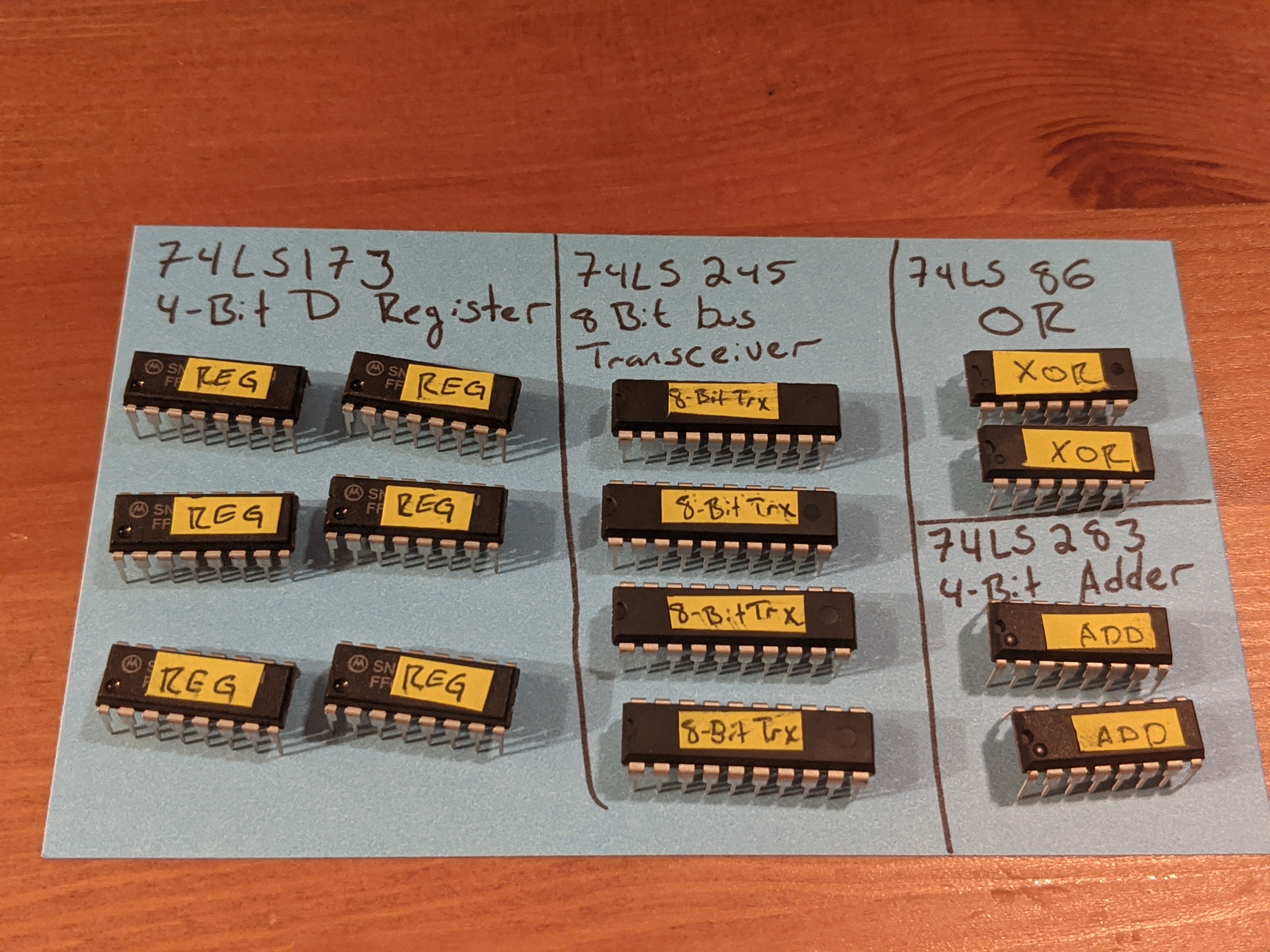
Each register uses :
- 2 4-bit 74LS173 (register)
- 1 8-bit 74LS245 (transceiver)
The remaining transceiver, OR gates, and adders in the picture will be used for the ALU.
The register chips are 4 bits each, which is why two are needed to store 8 bits total. They are wired together (clocks, read signal, output signal, etc) so that they can be used as a single logical unit. They are wired to always output their data so that we can see their state in the LED’s. That’s why the transceiver is needed to toggle writing that state to the bus when the computer needs to read from the register.
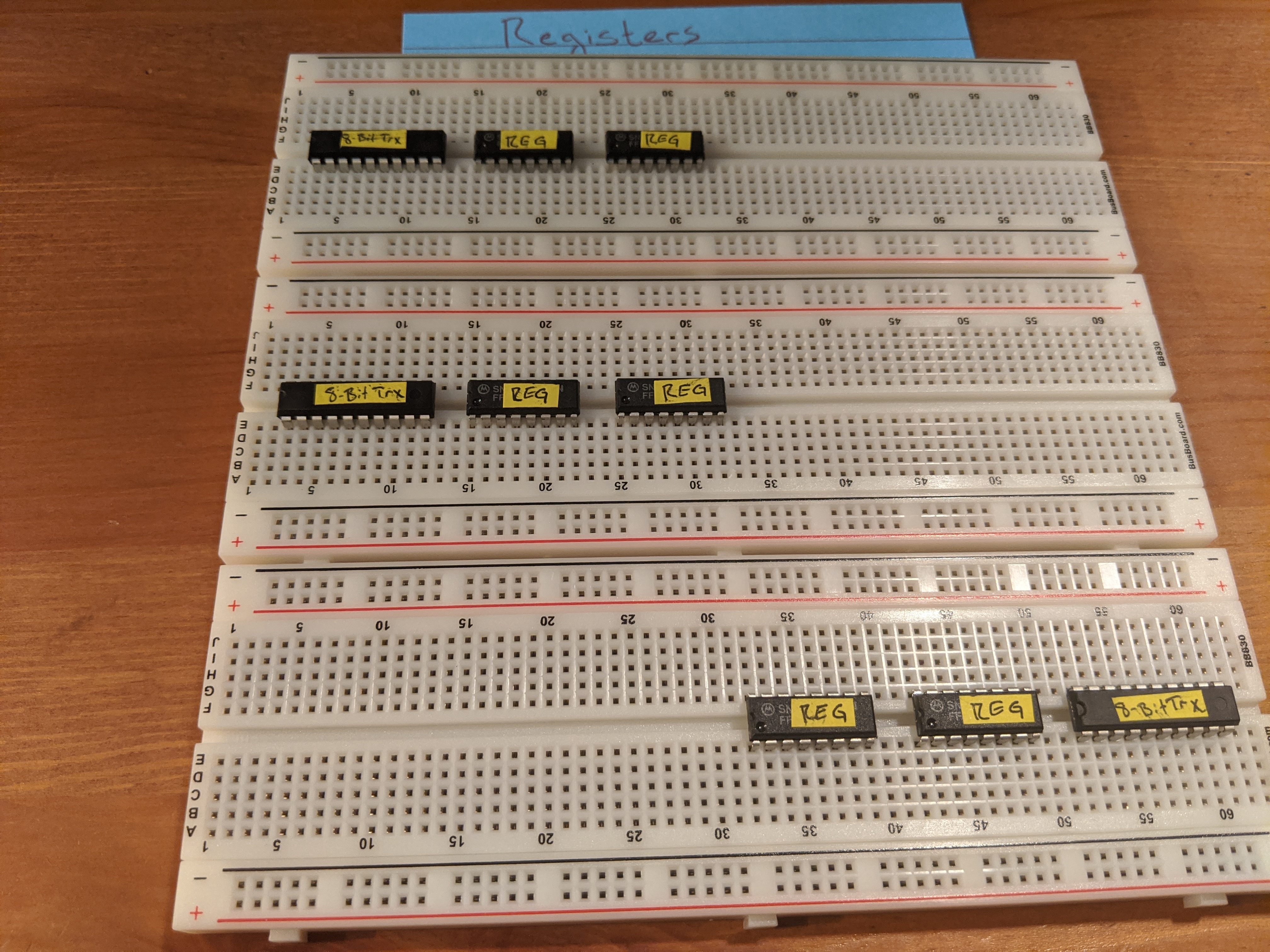
Each breadboard will be dedicated to a register. The top two will be the A and B registers, the bottom one will be used for the instruction register. The top two will be on the right side of the computer, the bottom one will be on the left. The transceiver chip will need to be connected to the bus (which will be in the middle) so it will be convenient to have that as close to the bus as possible (just to avoid messy wiring). Other than that, the three registers will be identical

Here we can see the connections keeping the pairs of register chips in sync with each other. The white wires (on the bottom) will be used as the clock input, the yellows are signals to read or clear data.
The rest of the work is to just wire up the 8 channels connecting the registers and transceivers.
LED’s
After wiring everything up and testing it by trying to read off of a mocked out bus … Nothing worked.
I spent hours following the video checking and rechecking my connections. Everything looked right. Reading r/beneater had a lot of posts about how important resistors are to the project despite being largely omitted from the videos. So I tried adding some in series to the LEDs to see if it would make a difference. Yes it did! Everything works now (well mostly, I still had a few wires crossed).
Now my question was: how do I want to lay out the LED’s and resistors? There’s not a lot of space when it’s just the LED’s, how am I supposed to cleanly sneak eight resistors in? My first attempt was to wire one resistor up in parallel with all of the LED’s. After checking with Reddit, it became apparent that the brightness of the LED’s would fluctuate depending how many were turned on at any given time. That didn’t sound great so back the drawing board.
I thought I could solder a row of male headers to some protoboard and then add the eight LEDs and resistors. I’d need to add a female header on the side to connect it to ground. This felt like it was just about in my skill set, so I gave it a try.
I figured I’d make four of these for the three registers and the ALU. The first step was to cut the protoboard down to size and then sand the edges so they were no longer sharp.

I cut the first one by scoring it with a razor blade and then snapping the ends off and then filing it down by hand. It took a while but in the end I had a nice result. Too bad I didn’t account for all the space I needed so I cut that one too small 🙁. It was late so I tabled it for the next day when I needed to break out the Dremel for another project anyway. This time I quickly cut the ends with the Dremel and then used the tool to do a first pass on the filing. I still finished it up by hand, but it was much faster.

Turns out that the coaster my in-laws brought me back from a trip a few years ago is the perfect size to hold a PCB. I used that as a base and then filed the sides down to be nice and smooth.
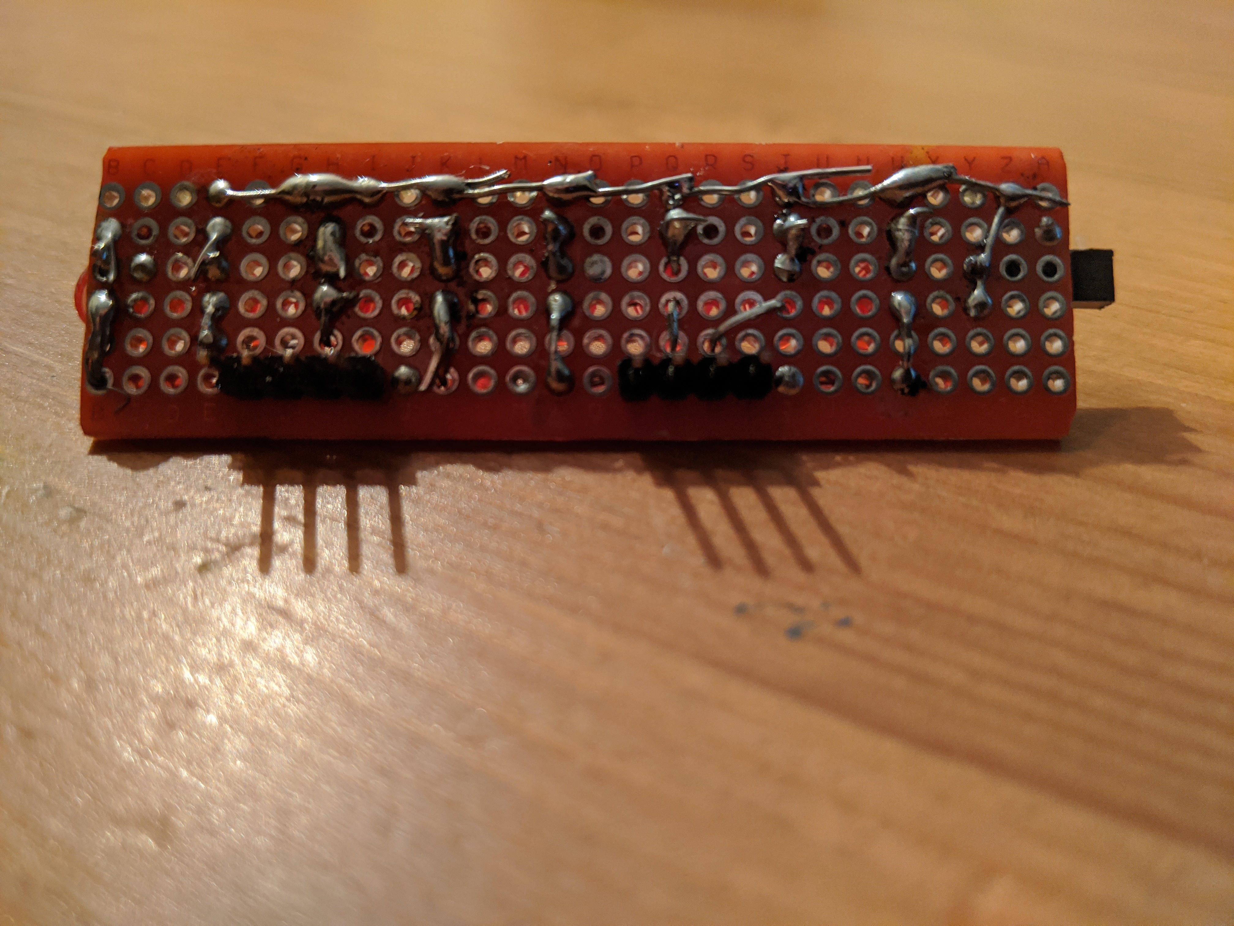
It took some trial and error to figure out the exact best way to solder everything in place. First I soldered two 4 pin male headers to the bottom of the board. They were spaced so they’d fit directly into the breadboard and connect to the registers.

Next I placed the LED on the top of the board and bent the anode lead back up through the board to solder to the top of header. This may have been easier if I had done it first and then soldered in the headers.
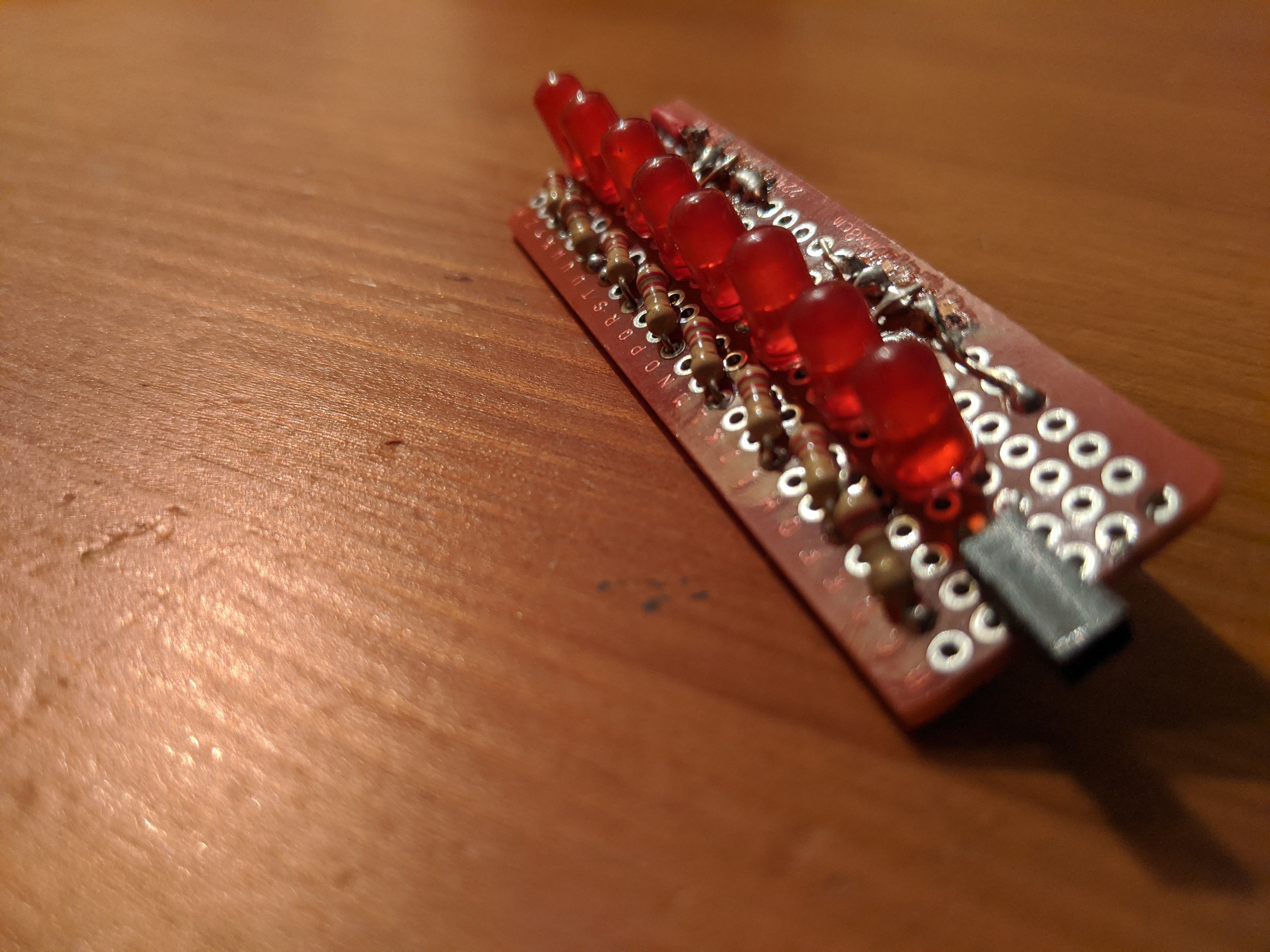
The cathode leads were then soldered to a resistor that was placed at an angle behind it. The angle allowed me to line up all of the resistors and just solder them together in a line leading to the female header on the end.
This mostly worked (I had a bad LED in the middle I had to swap out) but took me all day to do the soldering and testing for one LED strip. I could probably do the second strip a little faster now that I worked out some of the kinks. Instead of tackling that project, the next day I woke up and bought a few packs of LED’s with resistors built in. This would at least let me make progress in my tests without having to solder everything first. And maybe I can come up with a better plan.
I bought two types of LEDs. One kind has the resistor directly in the housing. I bought the mixed bag of colors as well as another hundred each of the reds and blues. These are 3mm instead of the 5mm ones I already had. Worst case scenario, I can work them into the same type of LED strip but have it take up less space and not have to solder in an additional resistor. The other type has the resistor soldered to the anode lead in a long wire. I got the mix pack for these as well, twenty each of white, red, blue, green, orange, and yellow. To simplify testing, I crimped Dupont connectors to the ends of a bunch of these in groups of four.

And with that, I was able to test all of the registers and bus at the same time.