
Breadboard Computer 1 Clock Module
I recently picked up Ben Eater’s 8-bit computer kit. The entire walk through for Ben’s computer can be found on youtube. The idea is to build a fully functioning 8-bit computer entirely on a breadboard. This should be a great learning experience for me considering I’ve never built anything particularly complicated in electronics. The first step is to create the clock module that powers the rest of the computer. The clock he’s designed has some interesting features
- Speed control using a potentiometer
- Step through mode - the clock advances when you manually press a button
- A circuit to switch between these two modes
- Halting the clock by setting the halt line high
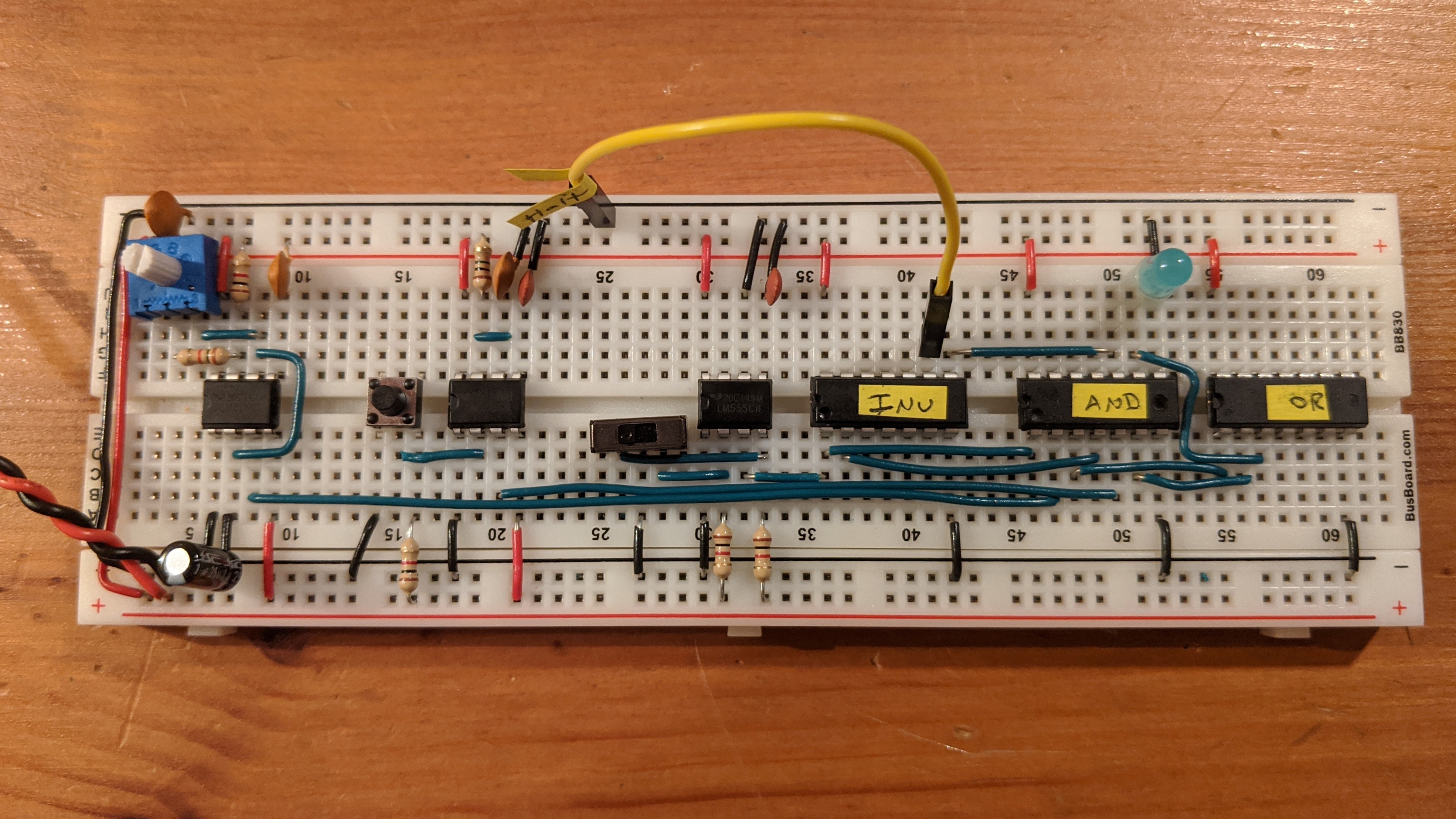
This is step 1 of the clock module, the variable speed portion. It uses a 555 timer to produce the square wave that powers the LED. That LED is eventually going to be removed from the board when the entire module is done, which is why it hasn’t been cut down.
The clock kit comes with pre-cut jumper wires that you can use. The drawback to them is that you can’t control the color for each length of wire. So I dug into the second kit to pull out the spools of 25 foot colored wires. I figure if I start with those wires now then the color coding will be consistent for the entire project. Not only that, but the red wires will be the same shade for the entire time.
That said, my biggest difficulty so far has been gettin’ gud at trimming the breadboard wires. Ben’s computer winds up being very neat and orderly with the wires. I’m hoping to get something close to that. I’ve tried breaking out my calipers to start measuring every wire I cut. That’s helped a bit. I’ve also tried bending the wires across the edge of the breadboard. I’ll keep it up and jot down any more notes as I try new methods.
After several hours of practice, I think I have a system.
- Cut a length of wire and strip some off the end (really doesn’t matter how much)
- Use the bare part as a grip as you pull off the remainder of the insulation
- Put the wire into the end of the breadboard, N-1 from the edge, where N is the number of breadboard holes you need the wire to travel.
- Bend the wire down 90 degrees exactly where it comes out of the breadboard (this ensures you leave the exact right amount of bare wire to go into the breadboard)
- Angle the rest of the wire going off the breadboard
- Cut a piece of insulation the same length as the distance from where the wire is placed in the board to the end of the breadboard
- Slip that insulation back on to the wire
- Bend the remaining bare wire 90 down, using the edge of the board as a guide
- Trim the excess wire just above the bottom of the breadboard
If you need a bunch of wires at once, measure out the right length past the edge of the breadboard and leave that piece of wire in. Then use that as the guide for other pieces you need to cut. There are eight holes at the bottom end of the board, so you can do eight wires pretty quick.
I used the above method to cut the wires for the rest of the work:
Manual Clock Advance
Debounced Switch
Switching Between Inputs
Before I got started with this slightly more complicated step, I sorted and labeled the chips:
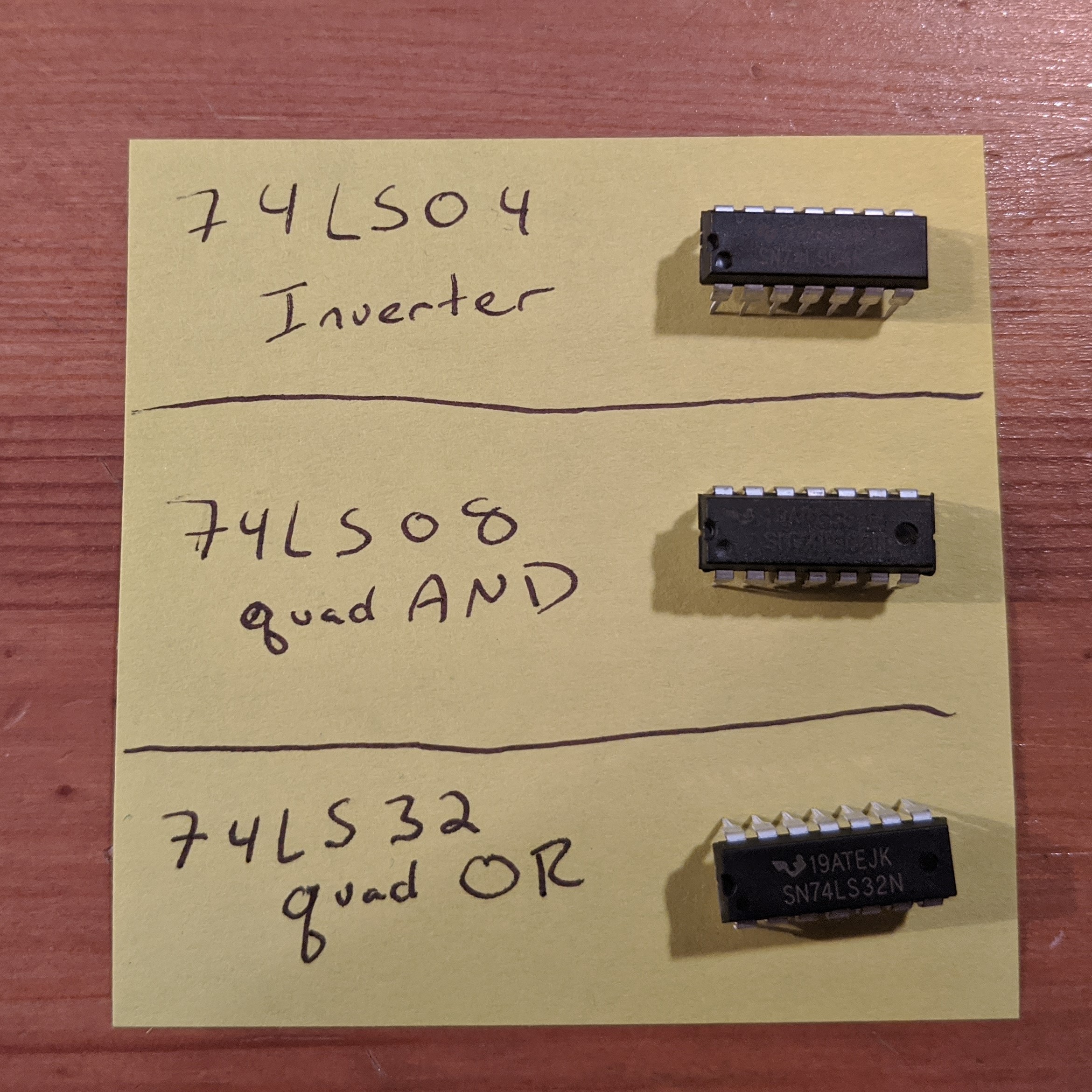
High tech, I know!
Today’s build was fun. It took most of the day (I really need to get better at cutting wires to length), but I did a lot of other things in there like make dinner and watch an episode of Better Call Saul.
For all of the details on how this works, I recommend checking out Ben’s youtube videos. He goes into more details than I could.