
Day 12 More Buttons and Some Bright Lights
I’ve been working on a project to create a Bluetooth “keyboard” with arcade buttons as the switches. Of course I want the buttons to light up. And I’d like to do this without using too many pins on my microcontroller. Naively if I had ten buttons (which I do) that would be 20 pins for the buttons and LED’s. The board I’m using has 21 pins. So that’s doable, but then doesn’t leave room for a lot of expansion (I also want a volume knob for instance…).
Button Matrix

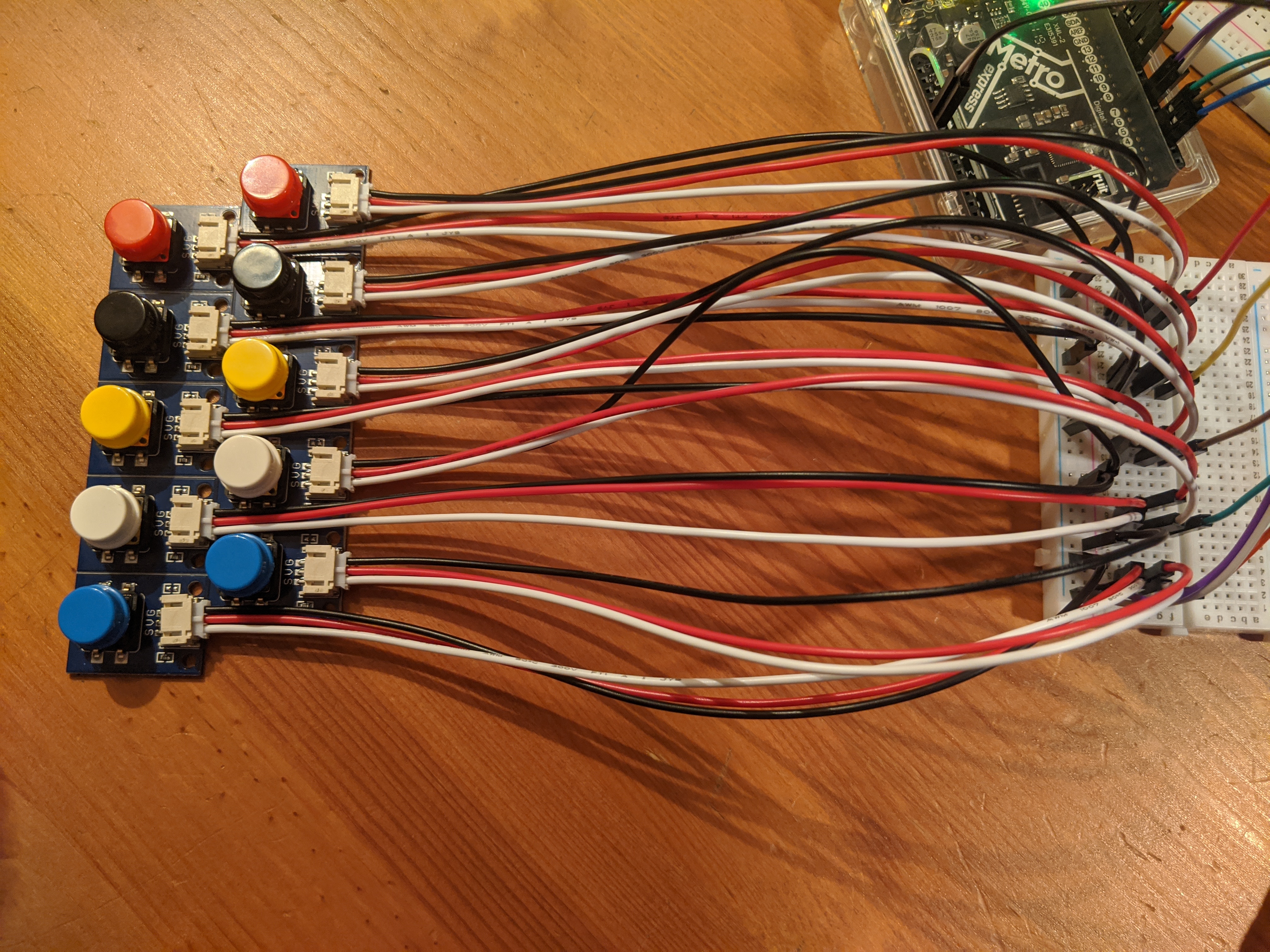
The solution I looked at was well documented around the web. I mostly used this sample from Adafruit since I was looking for examples using CircuitPython. I used a pair of Adafruit’s STEMMA wired buttonsto wire this up. The two rows of five colored buttons mimicked my real world project so it helped to visualize what I was doing. Each button has a 3 wire JST connection coming out of it with a white, black, and red wire. The white and black wires form a circuit when the button is pressed. For each board of five wires (my row), I connected all the black wires to the ground rail on a breadboard to wire them together (the rail wasn’t connected to ground). The other board was wired to the other power rail. For my columns, I just paired up each of the colors (the two blues, the two whites, etc). I plugged their corresponding white wires to a row on the breadboard. I believe that the red button is intended to be wired to a pull-up resistor which I didn’t need for this project. Just so they wouldn’t be in the way, I wired them up similar to the white wires.
Then to connect to the board, I plugged the two rows (the power rails) to pins
6 and 7 of my board. The columns were plugged into 9, 10, 11, 12, 13. I
pulled sample code from the Adafruit site and tweaked it to my configuration (2
rows instead of 4, 5 columns instead of 3, pin numbers, etc). The
adafruit_matrixkeypad library does most (all) of the heavy lifting here.
import time
import digitalio
import board
import adafruit_matrixkeypad

cols = [digitalio.DigitalInOut(x) for x in (board.D9, board.D10, board.D11, board.D12, board.D13)]
rows = [digitalio.DigitalInOut(x) for x in (board.D6, board.D7)]
keys = (("Blue 1", "White 1", "Yellow 1", "Black 1", "Red 1"),
        ("Blue 2", "White 2", "Yellow 2", "Black 2", "Red 2"))

keypad = adafruit_matrixkeypad.Matrix_Keypad(rows, cols, keys)

print ("Start pressing buttons")
while True:
    keys = keypad.pressed_keys
    if keys:
        print("Pressed: ", keys)

    time.sleep(0.1)
And it worked. Almost.
Whenever I pressed any button, it would show up as if the corresponding button on the next row was also pressed. After some hand wringing and checking all of my connections I realized that my breadboard actually has a short across those power rails. After pulling out all of the connections, rotating the board, and trying again, it worked just fine.
IC the Lights
Next I needed to get the lights working. I knew you easily create this type of output using shift registers. And as it happens I have about a dozen of 74HC595’s kicking around in a drawer. Problem is, I had no clue how to use them. I got lucky with some articles I happened to stumbled upon that had an example. Page 98 (according to the PDF, it’s 111 if you’re using the numbers on the bottom of page) of the Experiments Guide for Metrohas an article about adding “More LED’s”. That’s a good start for the wiring up. Only two problems.
- The sample code is in C not CircuitPython
- I want 10 LED’s not 8
Instead of figuring things out from scratch, I did a little googling and came across nuke66’s project which was pretty much exactly what I needed. Again, all I had to do was change the pins to what I had. The sample pretty much just toggled everything on or off. Controlling all of the lights at the same time is pretty easy, so why not something more fun? Let’s create a binary timer. Count from 1 to 256 (2 raised to the 8th) using the LED’s as outputs. So I made (minimal) changes to code. Sadly, I didn’t think to take a video of this marvel of modern electronics.
import time
import digitalio
import board
import simpleio

data = digitalio.DigitalInOut(board.D2)
data.direction = digitalio.Direction.OUTPUT

latch = digitalio.DigitalInOut(board.D4)
latch.direction = digitalio.Direction.OUTPUT

clk = digitalio.DigitalInOut(board.D3)
clk.direction = digitalio.Direction.OUTPUT

data = 0
while True:

    data += 1
    if (data == 256):
       data = 0

    # write to 595 chip
    latch.value = False
    simpleio.shift_out(data, clk, data)
    print("sending: {0:#010b} {0}".format(data),end="\n")
    latch.value = True
    time.sleep(0.1)
Next up: light them up based on which button is pressed. The button matrix already allows you to attach data to the button object which you get back when you query what’s been pressed. Instead of a meaningless label, why not just put in the id of the LED? Numbering each LED with a power of two will let me simply add up the keys pressed and send that out to shift register.
keys = ((1, 2, 4, 8, 16),
        (32, 64, 128, 256, 512))

# ...

while True
    keys = keypad.pressed_keys
    data = sum(keys)

    # ...
    simpleio.shift_out(data, clk, data)
That works except for the last two buttons which are greater than the default 8
bit limit of simpleio.shift_out. How do I wire in those two LEDs? I could
just wire in a second shift register with 3 more wires but that would be more
wires than it would take to just wire in two more LED’s, make the code more
complicated, and be really dumb.
The designers of the 595 agree with me. As it turns out, you can daisy chain multiple chips together. The bad news: I have no idea how to approach that. After some more google I found a bunch of videos that were helpful in that they showed what I wanted to do, but unhelpful in that it was a mess of wires and not clear what they were doing. OK, videos out. Guess I’ll have to read to get the answer here.
Mostly I was looking for a good diagram, which is what I found on protostack. Following this I saw that all I needed to do was:
- Connect pin 9 from the first shift register to pin 14 of the second one
- Connect pin 11 on both chips together
- Connect pin 12 on both chips together
I had started off on a half size breadboard so I needed to tear down everything I had to make room for the new chip and LED’s. In doing so I forgot to tie the OE (output enabled) to ground. This had some annoying and confusing results. Essentially the output would flicker because nothing was telling it whether to be on or off. The output would be more reliable if I held some of the wires (which really confused me). This reminded me of last time when I forgot to include a pull-up resistor in a button. I’d like to say that’s how I discovered the problem. But no, I went the classic route of taking it apart again and redoing all of the connections. I realized I didn’t have enough wires to connect the pins to ground and that’s what I had forgot.
Now that I had everything wired correctly, I still needed to figure out how to
control the additional input. If I tried sending anything higher than 255 I was
still not getting my new LED’s to light up. Reading through the CircuitPython
doco,
I saw that the shift_out function has a default paramter of bitcount set to
- Well… I want 16 bits. Setting that parameter worked.
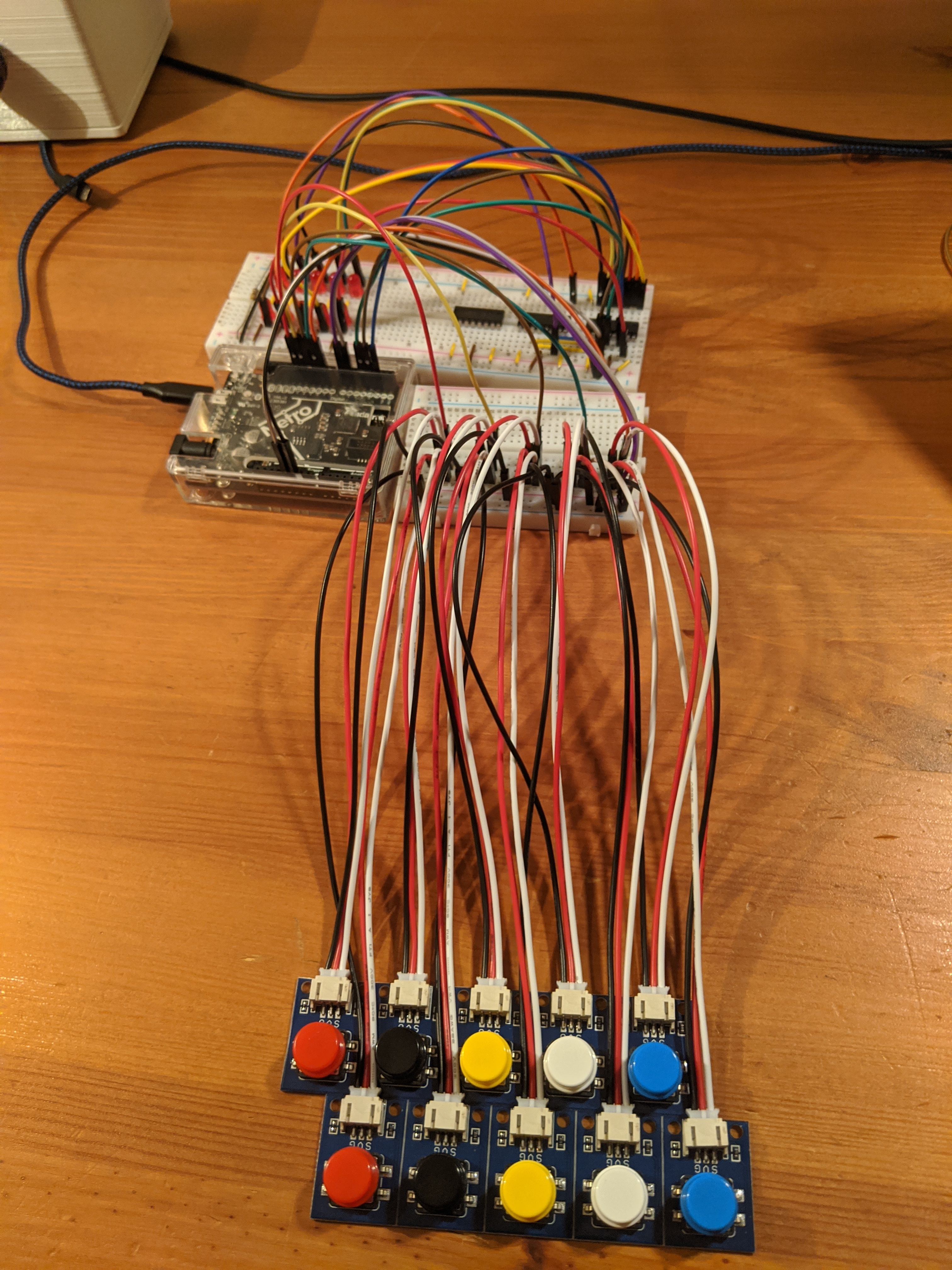
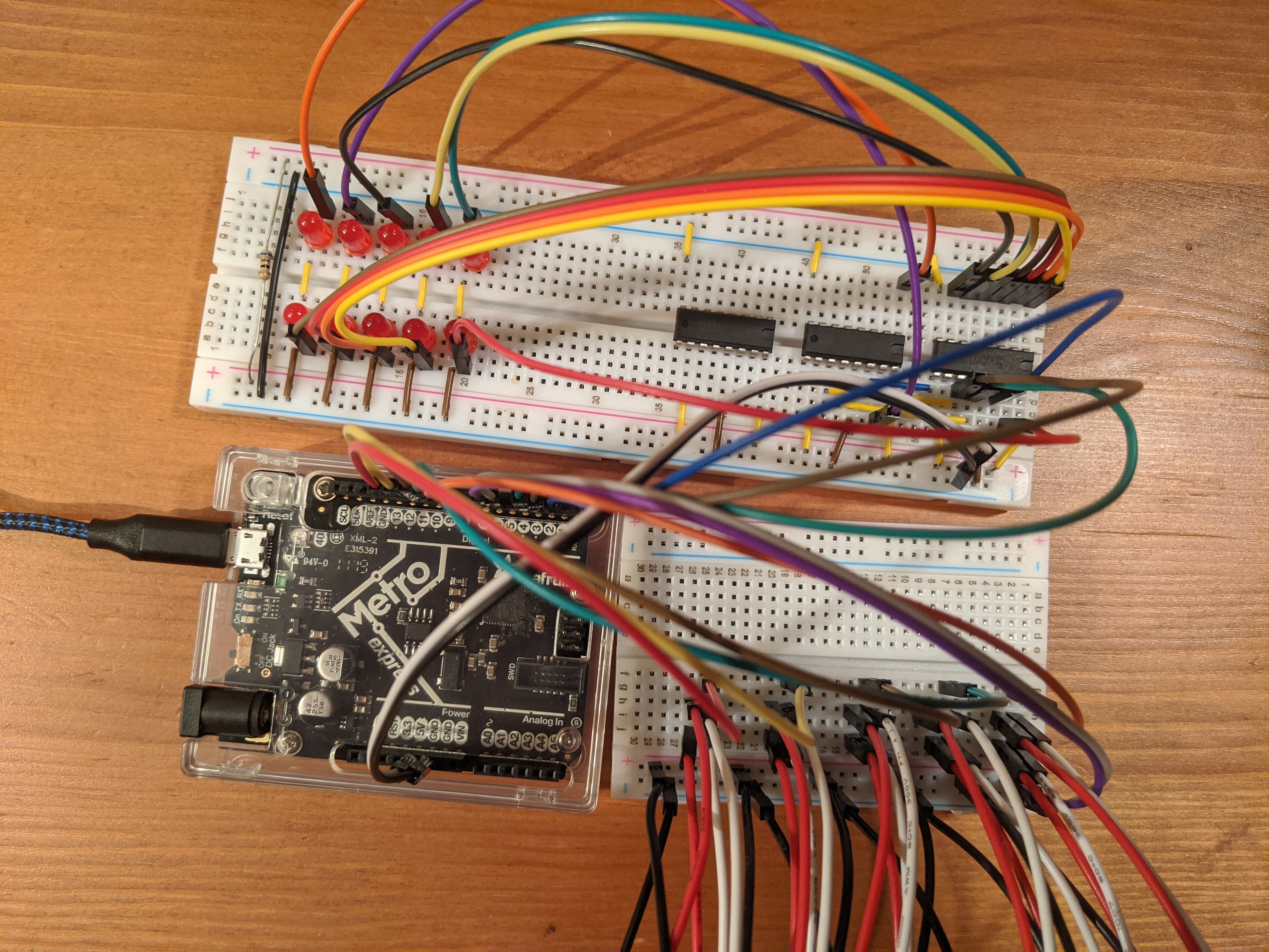
Completed
Here are some pictures of the “completed” project
Frizting diagram
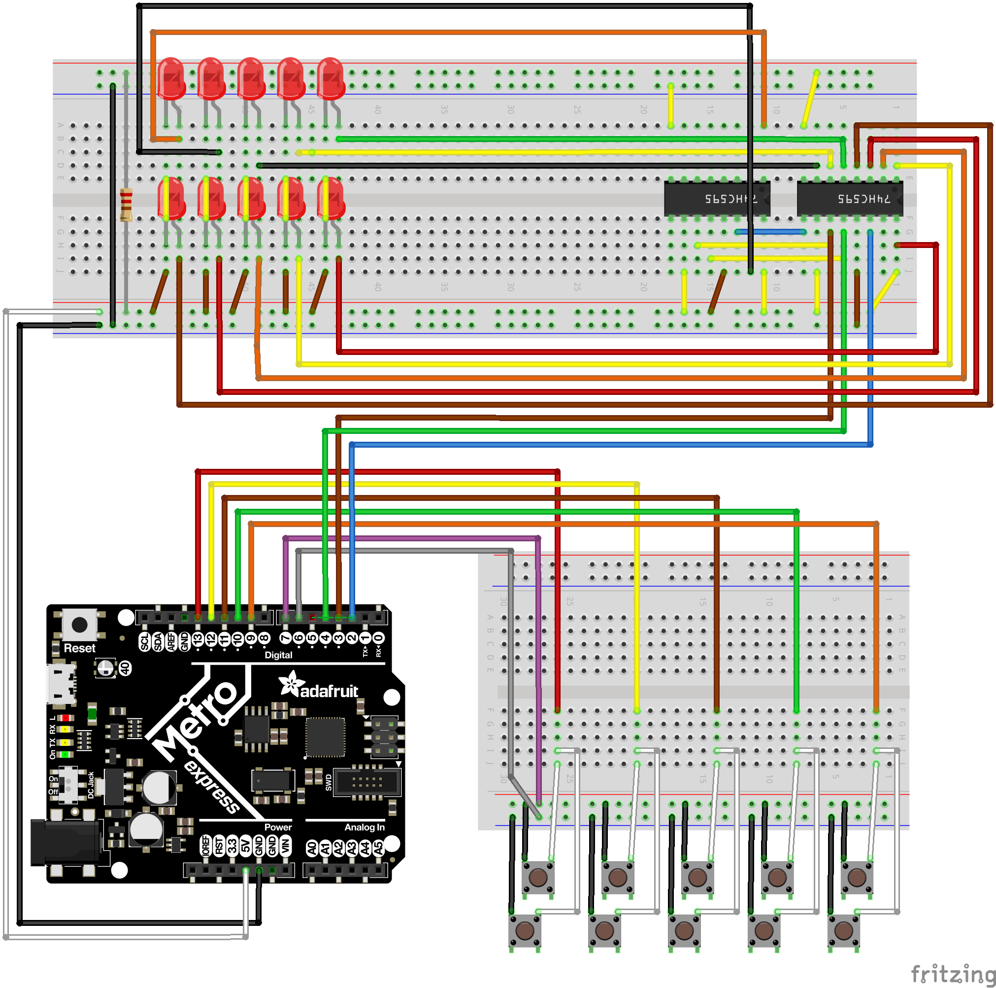
All of the code can be found in the Day 12 pull request in my repo.