
Day 11 Progress with Circuit Python
In my last go round I spent a lot of time mucking about with C++ to get things working. While searching through the Adafruit site, I came across a newer Bluetooth friendly device, this one capable of running CircuitPython. There’s even a tutorial for turning it into a Bluetooth keyboard. So I bought two. Due to Covid and the fact that Adafruit is focusing on producing PPE, it took an extra week or so to arrive. I got them this week and immediately started playing.
CircuitPython
CircuitPython is a version of Python that will run on a whole bunch of boards. Anything in the Adafruit line that is “Express” seems to be able to run it. Some Arduino boards support it as well.
Installation is pretty trivial on the Feather Express I got. The Adafruit site has a pretty thorough explanation. Pretty simply though, you plug it in to your computer. It will install itself and then automatically present itself as a file system.
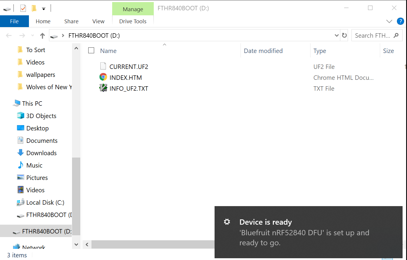
When that happens, go to the CircuitPython download
site, download the installation for your
board, and then drop that into the new folder. The board will restart and now
the root folder will have code.py. Write your python there. Whenever you save
it will automatically reload and run that script.
Hello World
The Hello World app is pretty easy (in fact it’s what comes in code.py by
default.
print("Hello World")
That’s it. This will just print “Hello World” to the serial bus. You see it by
opening up the serial port and watching it. While you can use the Serial
Monitor from the Arduino IDE, it’d be nice to no longer need that tool at all.
Luckily, PuTTY can handle serial ports as well as SSH. First you need to figure
out what port the device is connected to. If you have multiple devices they’ll
all connect to a different port, even if they aren’t plugged in at the same
time. Which is convenient since you can mentally associate a different port
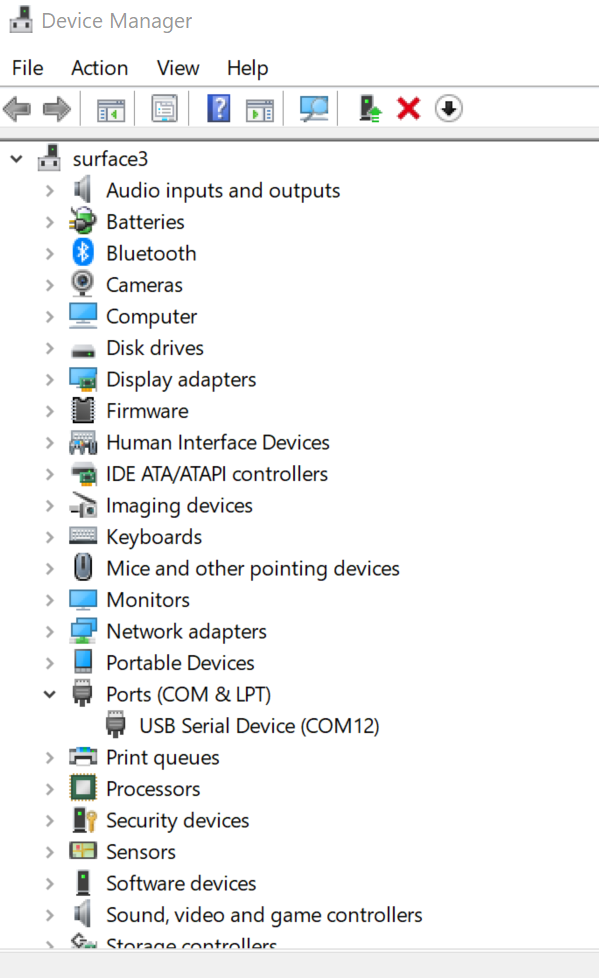
with each device. To determine which port it’s using open up the Device Manager
and expand the Ports (COM & LPT) node. It will be listed there. In my case,
it was port 12.
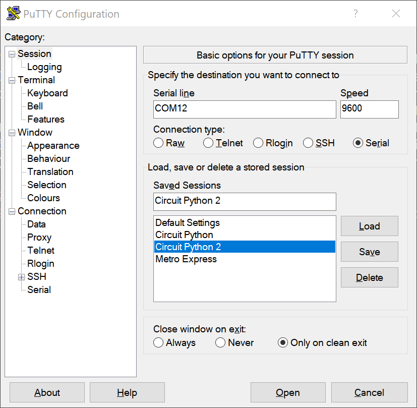
Fire up PuTTY, select the serial radio button, and enter COM12 in the
address bar. I left the speed at 9600 and it worked fine. Press connect and
you’re now connected to the console output of your board. You may need to
restart the program (just save it again).
I had some issues using vim, which was disappointing. Saving wouldn’t trigger a restart. I moved to Visual Studio Code. My preferred way to work is actually with both tools running, using VS Code for most editing tasks and switching to vim for specific types of edits. This actually works out pretty well. The only hiccup is that after saving in vim, I need to switch to VS Code and save it again if I want the code to run. It seems that the interpreter tries to evaluate the code before vim is done saving it.
Another nice touch is that any syntax or runtime errors automatically go to the serial output. For example, if you try to call a function that doesn’t exist, the board will stop evaluating and just dump the error out. Since you may not be looking at the serial output all the time, the board will flash it’s lights so you know there’s an error.
Back to the Box
Seeing as I already had a working set of buttons implemented in C++ on my button box, I wanted to try and rewrite that code in Python. It took me a couple of nights (and some frustration) to get it working in C++. On the other hand, it was about an hour or so to rewrite it all in Python. I had a couple of things going for me.
- I had better examples (including nearly exactly what I wanted) in CircuitPython
- I already compiled a list of all keystrokes I wanted to be able to perform
- Adafruit has put together a great set of libraries that makes the tasks I was looking to perform really easy
In addition to that, the feedback loop is super fast in CircuitPython. Write code. Save. Debug. Repeat. No compiling, no lengthy deploy process since it’s just a small script.
So not only was I able to bang out the code to get me back to where I was pretty easily, I was able to add the code to turn the rotary encoder (spinning knob) that was already on the box into a volume knob.
Today’s pull request has a bunch of files in it, but mostly because I checked in the python dependencies I need in order to get. I also included a couple of scripts that I wrote to just test specific things in isolation (like buttons or the rotary encoder).
Hardware
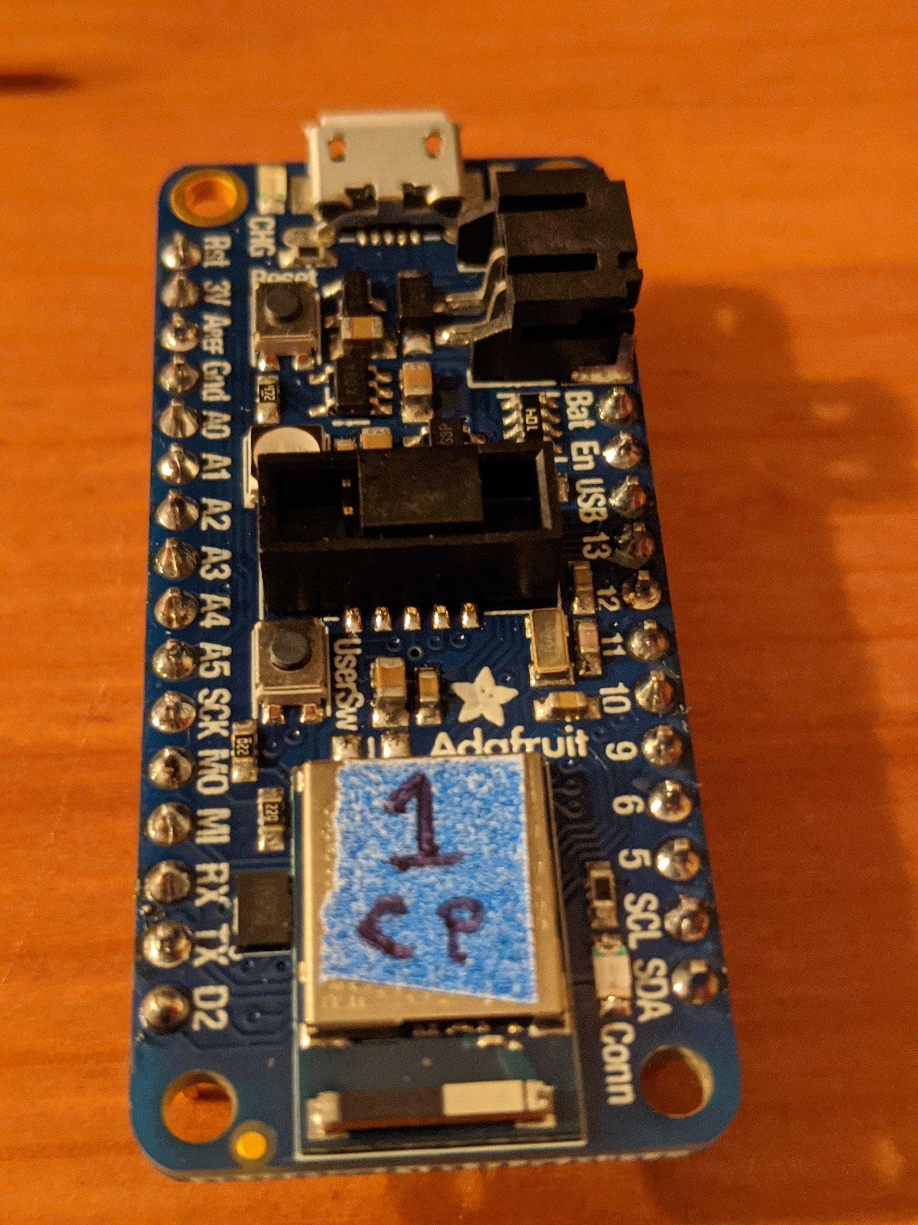
The hardware side was a little trickier. First, these boards don’t come with the headers attached. So I had to solder them myself. This is normally a scary point for me, but because of another project I had been working on, I was a little more confident going in. In fact I took this as an opportunity to solder a bunch of headers on a variety of boards I had lying around. This went pretty well (no shorts!) and didn’t take too long. I made some mistakes, but was able to fix them all.
This is what the board looked like when I was done. The blue sticker is there to differentiate it from other types of boards (which have another color sticker) and my other board of the same type (which has a different number written on it)
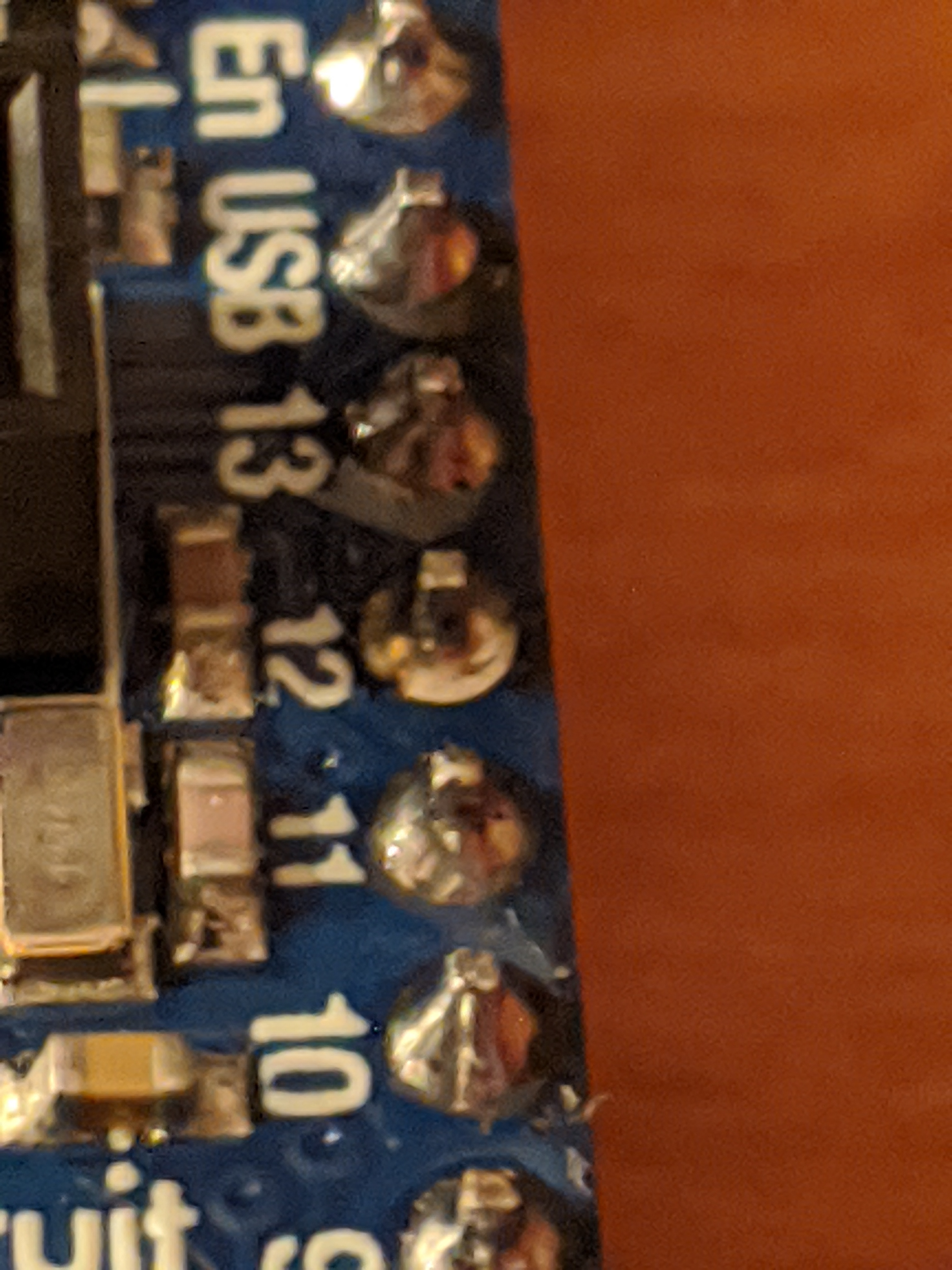
And here’s a close up of the soldering work.
My next problem was that the buttons seemed to be firing presses pretty
sporadically. After about half an hour of frustrated debugging, I realized that
the sample code I was using wasn’t explicitly setting the buttons to use a
pull-up resistor. Adding the line button_top_red.pull = Pull.UP for each
button fixed that! There was another way to handle this, plugging a third wire
from the button to the 3.3v pin on the board. The STEMMA
buttons I have for breadboarding do
have a third wire, and I was able to confirm that plugging it into power would
fix the issue. The reason I prefer the pull-up resistor solution was because I
have no idea where I’d attach a third wire to the buttons I have. This is a
hole in my understanding how buttons work. I’m fine with it for now, but will
need to figure this out at some point.
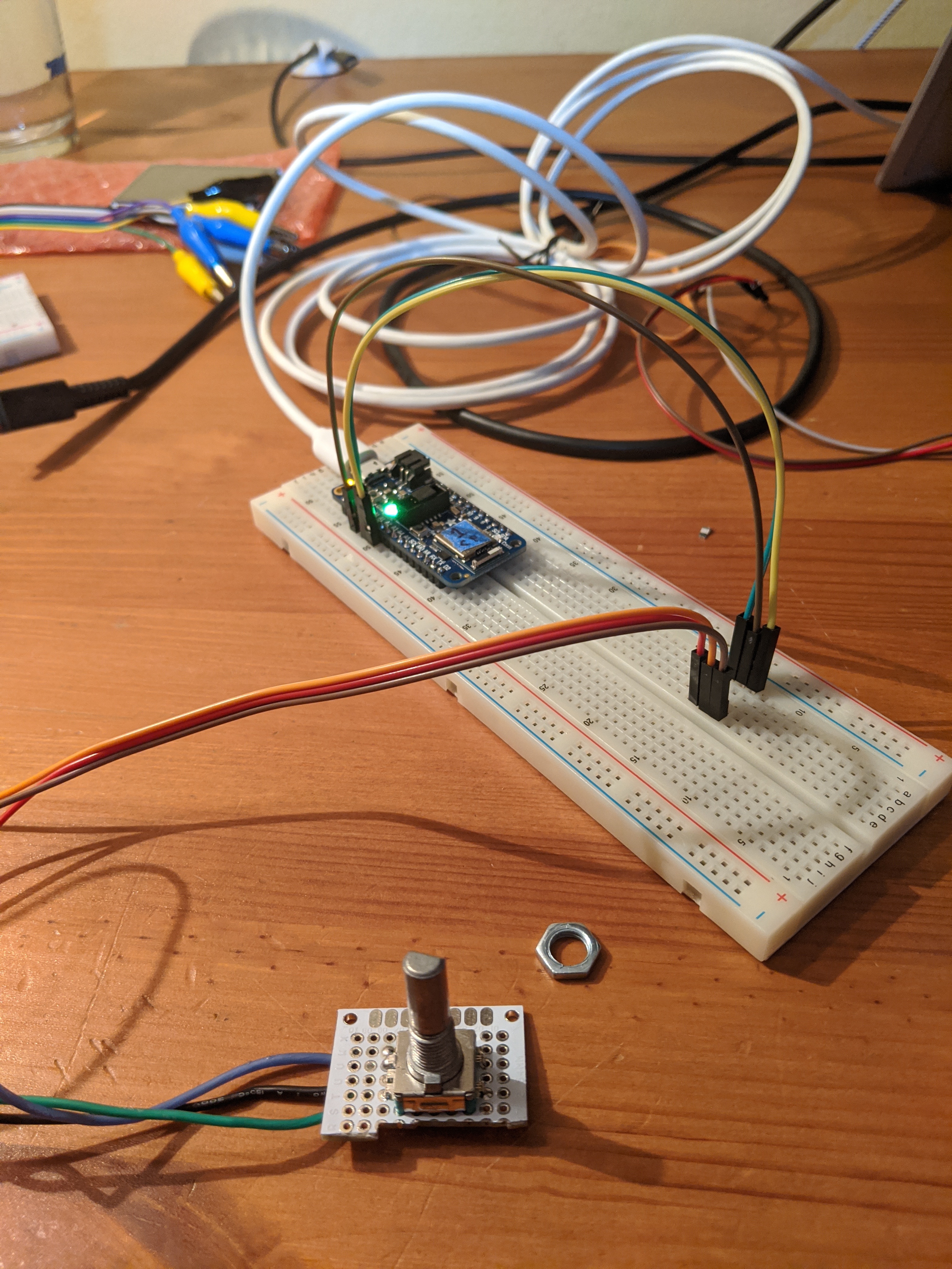
At this point, I was at parity with what I had before but I really wanted a volume knob. I found that I would absentmindedly spin the knob on the box even though I knew it didn’t do anything. I really wanted it to work. The code was easy, and it was easy to test with my breadboard friendly rotary encoder that I had. But the one I had in my box didn’t have the easy to attach to header pins. So I grabbed a piece of protoboard, cut it down to size a bit, and soldered the encoder to it along with some wires.

This is what it looks like from the top (and plugged into a breadboard for testing)
Conclusion
It was a really busy day, but much more productive than I have been in the past. Between the speed of developing with CircuitPython and confidence built up with the electronics aspects, I was able to take on more than I normally would and be confident that I would finish everything.